MULTI-MODE MANUAL TRANSAXLE SYSTEM, Diagnostic DTC:P0715

| DTC Code | DTC Name |
|---|---|
| P0715 | Input / Turbine Speed Sensor Circuit Malfunction |
DESCRIPTION
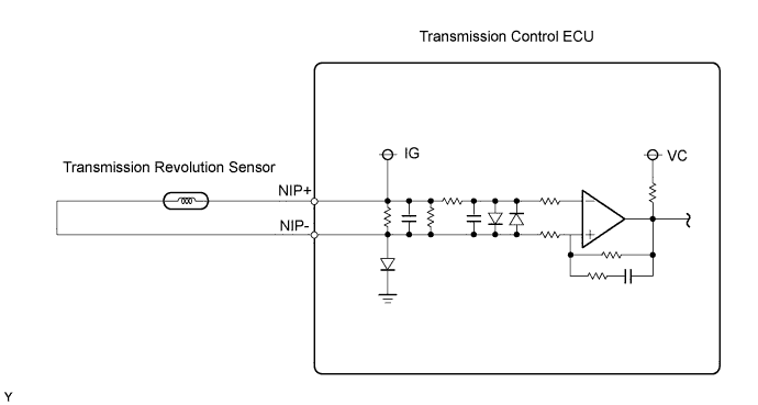
The transmission revolution sensor is mounted on the transmission. The transmission control ECU calculates the transmission input shaft speed using the sensor. When the input shaft rotates, the sensor generates a pulse signal and sends the signal to the transmission control ECU. The ECU calculates the input shaft speed based on the signal. If the input shaft speed falls below a threshold despite the vehicle running, the ECU interprets this as a malfunction in the transmission revolution sensor circuit. The ECU sets the DTC and illuminates the multi-mode manual transmission warning light.
| DTC No. | DTC Detection Conditions | Trouble Areas |
|---|---|---|
| P0715 | The transmission control ECU detects the following conditions simultaneously: (1 trip detection logic)
|
|
WIRING DIAGRAM
INSPECTION PROCEDURE
Tech Tips
When the DTC is set, check the transmission input revolution by selecting the following menu items on an intelligent tester: Powertrain / Multi-Mode M/T / Data List / Input Revolution.
| Items [Abbreviation] |
Measurement Items: Display | Normal Conditions | Diagnostic Notes |
|---|---|---|---|
| Input Revolution [Input Rev.] |
Transmission input revolution: Min.: 0 rpm, Max.: 12,800 rpm |
0 rpm: Vehicle stationary | When input revolution signal malfunctions, value calculated from vehicle speed signal displayed |
PROCEDURE
-
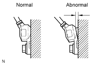
CHECK SENSOR INSTALLATION
-
Check the transmission revolution sensor installation.
OK Sensor is installed correctly.
NG 
SECURELY REINSTALL SENSOR
OK 
-
-
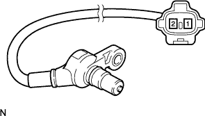
INSPECT TRANSMISSION REVOLUTION SENSOR
-
Disconnect the transmission revolution sensor connector.
-
Measure the resistance between the terminals of the transmission revolution sensor connector.
Standard Resistance Tester Connections Specified Conditions 1 - 2 560 to 680 Ω at 20°C (68°F) -
Reconnect the transmission revolution sensor connector.
NG
REPLACE TRANSMISSION REVOLUTION SENSOR
OK
-
-
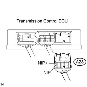
CHECK HARNESS AND CONNECTOR (TRANSMISSION REVOLUTION SENSOR - TRANSMISSION CONTROL ECU)
-
Disconnect the transmission control ECU connector.
-
Measure the resistance between the terminals of the ECU connector.
Standard Resistance Tester Connections Specified Conditions 1 - 2 560 to 680 Ω at 20°C (68°F) -
Reconnect the transmission control ECU connector.
NG
REPAIR OR REPLACE HARNESS OR CONNECTOR
OK 
REPLACE TRANSMISSION CONTROL ECU ASSEMBLY
-