MULTI-MODE MANUAL TRANSAXLE SYSTEM, Diagnostic DTC:P0562

| DTC Code | DTC Name |
|---|---|
| P0562 | System Voltage |
DESCRIPTION
The battery supplies electricity to the transmission control ECU even when the ignition switch is off. This power allows the transmission control ECU to store data such as the learning value of actuators, DTC history and freeze frame data. If the battery voltage falls below a minimum level, these memories are cleared and the transmission control ECU determines that there is a malfunction in the power supply circuit. If an open or short circuit occurs in the +B circuit while the ignition switch is to ON, the transmission control ECU stops operating immediately.
| DTC No. | DTC Detection Condition | Trouble Area |
|---|---|---|
| P0562 | +B terminal voltage 7.0 V or less for 0.5 seconds or more (1-trip detection logic) |
|
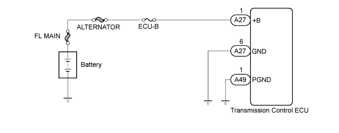
WIRING DIAGRAM
INSPECTION PROCEDURE
Note
Inspect the fuses for circuits related to this system before performing the following inspection procedure.
PROCEDURE
-
CHECK HARNESS AND CONNECTOR (TRANSMISSION CONTROL ECU ASSEMBLY - BATTERY, BODY GROUND)
-
Disconnect the A27 and A49 transmission control ECU connectors.
-
Measure the resistance according to the value(s) in the table below.
Standard Resistance Tester Connection Condition Specified Condition A27-6 (GND) - Body ground Always Below 1 Ω A49-1 (PGND) - Body ground Always Below 1 Ω -
Measure the voltage according to the value(s) in the table below.
Standard Voltage Tester Connection Condition Specified Condition A27-1 (+B) - A27-6 (GND) Always 11 to 14 V
NG 
REPAIR OR REPLACE HARNESS OR CONNECTOR
OK 
-
-
REPLACE TRANSMISSION CONTROL ECU
-
Replace the transmission control ECU Click here.
NEXT
-
-
PERFORM INITIALIZATION
-
Perform the initialization and learning for multi-mode manual transaxle system Click here.
NEXT 
END
-