MULTI-MODE MANUAL TRANSAXLE SYSTEM, Diagnostic DTC:P0500

| DTC Code | DTC Name |
|---|---|
| P0500 | Vehicle Speed Sensor "A" |
DESCRIPTION
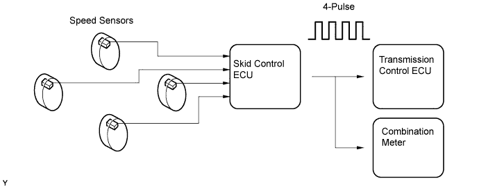
Vehicles, which are equipped with the ABS (Anti-lock Brake System) or VSC (Vehicle Stability Control), detect the vehicle speed using the skid control ECU and wheel speed sensor. The wheel speed sensor monitors the wheel rotation speed and sends a signal to the skid control ECU. The skid control ECU converts the wheel speed signal into a 4-pulse signal and transmits it to the transmission control ECU. The transmission control ECU determines the vehicle speed based on the frequency of the pulse signal.
| DTC No. | DTC Detection Condition | Trouble Area |
|---|---|---|
| P0500 | The transmission control ECU detects the following conditions simultaneously for 4 seconds or more: (1-trip detection logic)
|
|
WIRING DIAGRAM
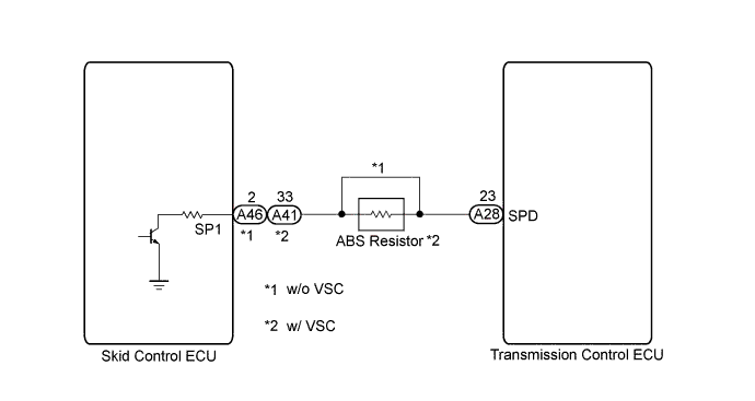
When a DTC P0500 is output, a ground short in the wiring of terminal SPD or an internal ground short in the relevant ECU is suspected.
INSPECTION PROCEDURE
PROCEDURE
-
READ VALUE USING INTELLIGENT TESTER (VEHICLE SPEED)
-
Connect the intelligent tester to the DLC3.
-
Turn the ignition switch to ON.
-
Turn the tester on.
-
Enter the following menus: Powertrain / Multi-Mode M/T / Data List / Vehicle Speed and Vehicle Speed Signal.
-
Drive the vehicle.
-
Check that the speed displayed on the tester screen is the same as the one indicated on the combination meter.
Tester Display Measurement Item/Range Normal Condition Diagnostic Note Vehicle Speed
[Vehicle Spd]
Vehicle speed:
Min.: 0 km/h, Max.: 255 km/h
0 km/h (0 mph): Vehicle stationary Approximately same value as combination meter display When vehicle speed signal malfunctions, speed value calculated from transmission input revolution signal displayed Vehicle Speed Signal
[Vehicle Spd Sig]
Vehicle speed signal:
Min.: 0 km/h, Max.: 327.675 km/h
0 km/h (0 mph): Vehicle stationary When vehicle speed signal malfunctions, speed value calculated from transmission input revolution signal displayed OK The speed displayed on the tester screen is approximately equal to the actual speed.
NG 
CHECK OPERATION OF SPEEDOMETER Click here
OK 
CHECK FOR INTERMITTENT PROBLEMS
-
-
CHECK OPERATION OF SPEEDOMETER
-
Drive the vehicle and check if the function of the speedometer in the combination meter is normal.
OK The actual vehicle speed and the speed indicated on the speedometer are the same. Tech Tips
The vehicle speed sensor is functioning normally when the indication on the speedometer is normal.
NG 
GO TO BRAKE CONTROL SYSTEM
OK 
-
-
CHECK HARNESS AND CONNECTOR (TRANSMISSION CONTROL ECU - SKID CONTROL ECU)
-
Disconnect the A28 transmission control ECU connector.
-
Disconnect the A46 skid control ECU connector (w/o VSC System).
-
Disconnect the A41 skid control ECU connector (w/ VSC System).
-
Measure the resistance according to the value(s) in the table below.
Standard Resistance w/o VSC System: Tester Connection Condition Specified Condition A28-23 (SPD) - A46-2 (SP1) Always Below 1 Ω A28-23 (SPD) or A46-2 (SP1) - Body
ground
Always 10 kΩ or higher Standard Resistance w/ VSC System: Tester Connection Condition Specified Condition A28-23 (SPD) - A41-33 (SP1) Always 19 to 22 Ω A28-23 (SPD) or A41-33 (SP1) - Body
ground
Always 10 kΩ or higher -
Reconnect the transmission control ECU connector.
-
Reconnect the skid control ECU connector.
NG
REPAIR OR REPLACE HARNESS OR CONNECTOR
OK
-
-
REPLACE TRANSMISSION CONTROL ECU
-
Replace the transmission control ECU Click here.
NEXT
-
-
PERFORM INITIALIZATION
-
Perform the initialization and learning for multi-mode manual transaxle system Click here.
NEXT
END
-