MULTI-MODE MANUAL TRANSAXLE SYSTEM, Diagnostic DTC:P0715

| DTC Code | DTC Name |
|---|---|
| P0715 | Input / Turbine Speed Sensor Circuit Malfunction |
DESCRIPTION
The transmission revolution sensor is mounted on the transaxle. The transmission control ECU calculates the transaxle input shaft speed using the sensor. When the input shaft rotates, the sensor generates a pulse signal and sends the signal to the transmission control ECU. The ECU calculates the input shaft speed based on the signal. If the input shaft speed falls below a threshold despite the vehicle running, the ECU interprets this as a malfunction in the transmission revolution sensor circuit. The ECU sets the DTC and illuminates the multi-mode manual transaxle warning light.
| DTC No. | DTC Detection Condition | Trouble Area |
|---|---|---|
| P0715 | The transmission control ECU detects the following conditions simultaneously: (1-trip detection logic)
|
|
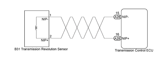
WIRING DIAGRAM
INSPECTION PROCEDURE
PROCEDURE
-
INSPECT SENSOR INSTALLATION (TRANSMISSION REVOLUTION SENSOR)
-
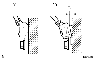
Text in Illustration *a Normal *b Abnormal *c Clearance Check the transmission revolution sensor installation.
OK Sensor is installed correctly.
NG 
SECURELY INSTALL OR REPLACE SENSOR
OK 
-
-
INSPECT TRANSMISSION REVOLUTION SENSOR
-
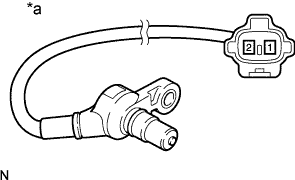
Text in Illustration *a Component without harness connected
(Transmission revolution sensor)
Disconnect the B31 transmission revolution sensor connector.
-
Measure the resistance according to the value(s) in the table below.
Standard Resistance Tester Connection Condition Specified Condition 1 (NIP-) - 2 (NIP+) 20°C (68°F) 560 to 680 Ω
NG
REPLACE TRANSMISSION REVOLUTION SENSOR Click here
OK
-
-
CHECK HARNESS AND CONNECTOR (TRANSMISSION REVOLUTION SENSOR - TRANSMISSION CONTROL ECU)
-
Reconnect the B31 transmission revolution sensor connector.
-
Disconnect the A28 transmission control ECU connector.
-
Measure the resistance according to the value(s) in the table below.
Standard Resistance Tester Connection Condition Specified Condition A28-15 (NIP-) - A28-16 (NIP+) 20°C (68°F) 560 to 680 Ω A28-15 (NIP-) - Body ground Always 10 kΩ or higher A28-16 (NIP+) - Body ground Always 10 kΩ or higher
NG
REPAIR OR REPLACE HARNESS OR CONNECTOR
OK
-
-
REPLACE TRANSMISSION CONTROL ECU
-
Replace the transmission control ECU Click here.
NEXT
-
-
PERFORM INITIALIZATION
-
Perform the initialization and learning for multi-mode manual transaxle system Click here.
NEXT 
END
-