DIFFERENTIAL OIL SEAL INSTALLATION

-
INSTALL TRANSMISSION CASE OIL SEAL
-
Coat a new oil seal lip with MP grease.
-
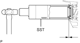
Using SST and a hammer, install the transmission case oil seal.
- SST
- 09316-60011 ( 09316-00011 )
Drive in depth 2.1 to 3.1 mm (0.0827 to 0.122 in.) Note
Do not damage the oil seal lip.
-
-
INSTALL TRANSAXLE CASE OIL SEAL
-
Coat a new oil seal lip with MP grease.
-
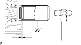
Using SST and a hammer, install the transaxle case oil seal.
- SST
- 09636-20010
Drive in depth 1.7 to 2.7 mm (0.0670 to 0.106 in.) Note
Do not damage the oil seal lip.
-
-
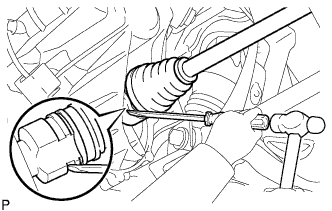
INSTALL FRONT DRIVE SHAFT ASSEMBLY LH
-
Coat the spline of the inboard joint shaft assembly with transaxle oil.
-
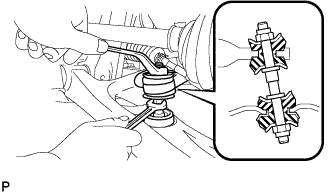
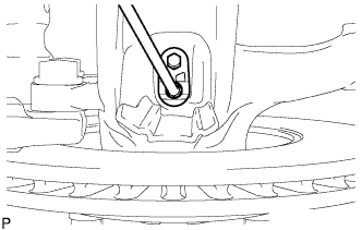
Align the shaft splines and install the drive shaft assembly with a screwdriver and hammer.
Note
-
Face the snap ring cut area downward.
-
Do not damage the oil seal.
-
Do not damage the front drive shaft assembly boot.
Tech Tips
Whether the front drive shaft assembly is securely driven in or not can be confirmed from the brass bar reaction force or sound.
-
-
-
INSTALL FRONT DRIVE SHAFT ASSEMBLY RH
Tech Tips
The installation procedure for the RH side is the same as that for the LH side.
-
INSTALL FRONT AXLE ASSEMBLY LH
-
Push the front axle assembly out of the vehicle to align the spline of the front drive shaft assembly with the front axle assembly and insert the front axle assembly.
Note
-
Do not push the front axle assembly further out of the vehicle than is necessary.
-
Do not damage the oil seal.
-
Do not damage the front drive shaft assembly boot.
-
Do not damage the speed sensor rotor.
-
Check for any foreign matter on the speed sensor rotor and insertion part.
-
-
-
INSTALL FRONT AXLE ASSEMBLY RH
Tech Tips
The installation procedure for the RH side is the same as that for the LH side.
-
INSTALL FRONT SUSPENSION LOWER ARM SUB-ASSEMBLY LH
-
Push the front suspension lower arm No. 1 downward, install the front lower ball joint and tighten the castle nut and a new clip.
- Torque:
- 98 N*m { 1,000 kgf*cm, 72 ft.*lbf }
Note
Retighten the castle nut and clip within a turning angle of 60° after aligning the hole of the clip with the castle nut.
-
-
INSTALL FRONT SUSPENSION LOWER ARM SUB-ASSEMBLY RH
Tech Tips
The installation procedure for the RH side is the same as that for the LH side.
-
INSTALL FRONT STABILIZER BAR
-
Install the stabilizer bar front with the 2 cushion retainers, 2 cushions and a nut, as shown in the illustration.
Note
Be sure to install the cushion and retainer in the correct direction.
-
Tighten the nut with a spanner (10 mm).
- Torque:
- 18 N*m { 184 kgf*cm, 13 ft.*lbf }
-
-
INSTALL TIE ROD END SUB-ASSEMBLY LH
-
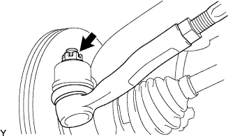
Connect the tie rod end to the steering knuckle and install it with the castle nut and a new cotter pin.
- Torque:
- 33 N*m { 336 kgf*cm, 24 ft.*lbf }
Note
Retighten the castle nut and cotter pin within a turning angle of 60° after aligning the hole of the cotter pin with the castle nut.
-
-
INSTALL TIE ROD END SUB-ASSEMBLY RH
Tech Tips
The installation procedure for the RH side is the same as that for the LH side.
-
INSTALL FRONT AXLE SHAFT NUT LH
-
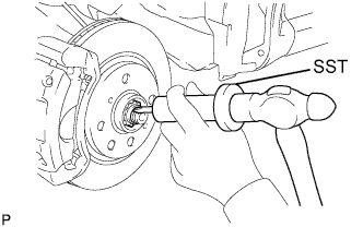
Install a new front axle hub nut.
- Torque:
- 216 N*m { 2,202 kgf*cm, 160 ft.*lbf }
-
Using a hammer and chisel, stake the front axle hub nut.
-
-
INSTALL FRONT AXLE SHAFT NUT RH
Tech Tips
The installation procedure for the RH side is the same as that for the LH side.
-
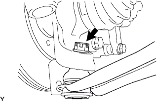
INSTALL FRONT SPEED SENSOR LH
-
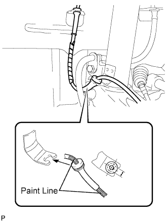
Connect the speed sensor wire to the shock absorber assembly.
Note
Insert a rubber grommet into the bracket with the painted line placed between the bracket cutouts.
-
Install the bolt and speed sensor front onto the steering knuckle.
- Torque:
- 8.0 N*m { 82 kgf*cm, 71 in.*lbf }
Note
-
Do not damage the speed sensor.
-
Keep the speed sensor free of any foreign material.
-
Do not twist the sensor wire when installing the speed sensor.
-
-
INSTALL FRONT SPEED SENSOR RH
Tech Tips
The installation procedure for the RH side is the same as that for the LH side.
-
INSTALL FRONT WHEELS
- Torque:
- 103 N*m { 1050 kgf*cm, 76 ft.*lbf }
-
ADD TRANSAXLE OIL
-
INSPECT MANUAL TRANSAXLE OIL
-
Stop the vehicle in a level place.
-
Remove the manual transaxle filler plug and the gasket.
-
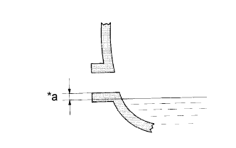
Text in Illustration *a 0 to 5 mm (0 to 0.20 in.) Check that the oil surface is within 5 mm (0.20 in.) of the bottom of the manual transaxle filler plug opening.
Note
-
Excessively large or small amounts of oil may cause trouble.
-
After replacing the oil, drive the vehicle and check the oil level again.
-
-
Check for oil leakage if the oil level is low.
-
Install the manual transaxle filler plug and a new gasket.
- Torque:
- 39 N*m { 400 kgf*cm, 29 ft.*lbf }
-
-
INSPECT FRONT WHEEL ALIGNMENT
-
INSPECT FOR MANUAL TRANSAXLE OIL LEAK