MANUAL TRANSAXLE ASSEMBLY REASSEMBLY

-
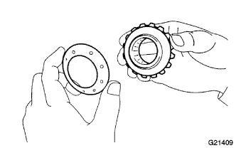
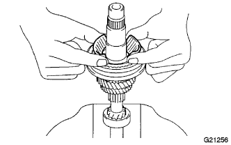
INSTALL FRONT DIFFERENTIAL CASE
-
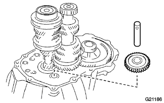
Install appropriate thrust washers and side gears.
Refer to the table below and select thrust washers that bring the backlash to within the specifications. Select washers of the same size for both sides.
Standard backlash 0.05 to 0.20 mm (0.0020 to 0.0079 in.) Thrust Washer Thickness Thickness
mm (in.)
Thickness
mm (in.)
0.50 (0.0197) 0.75 (0.0295) 0.55 (0.0217) 0.80 (0.0315) 0.60 (0.0236) 0.85 (0.0335) 0.65 (0.0256) 0.90 (0.0354) 0.70 (0.0276) 0.95 (0.0374) -
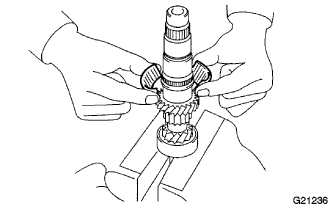
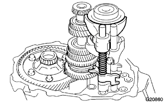
Install the thrust washers and side gears into the differential case.
-
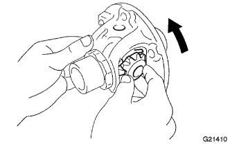
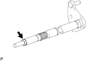
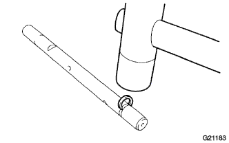
Install the pinion shaft.
-
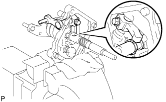
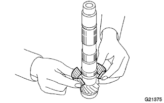
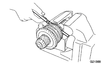
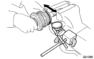
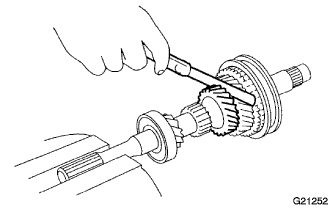
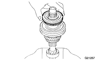
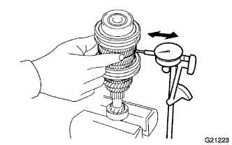
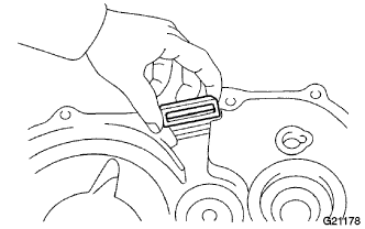
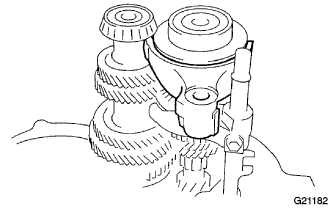
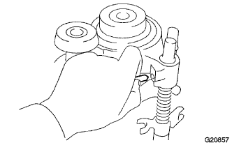
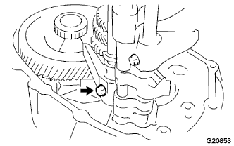
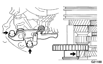
Using a dial indicator, check the side gear backlash.
Measure the side gear backlash while holding one pinion gear against the differential case.
Standard backlash 0.05 to 0.20 mm (0.0020 to 0.0079 in.) If the backlash is not within the specifications, install a thrust washer of a different thickness.
-
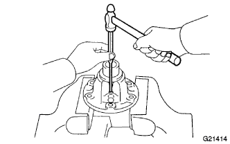
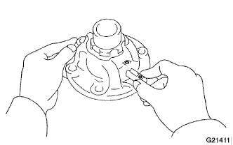
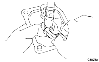
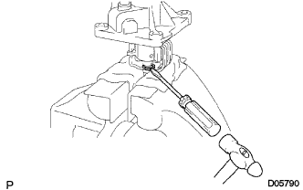
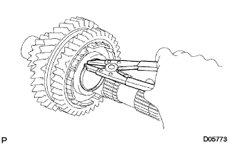
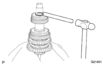
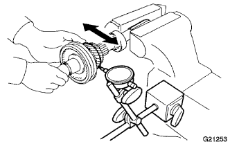
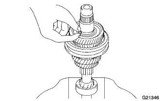
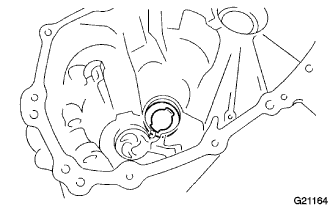
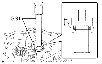
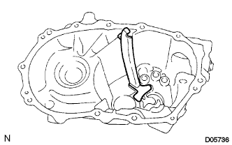
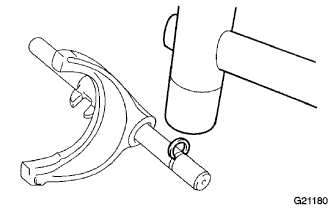
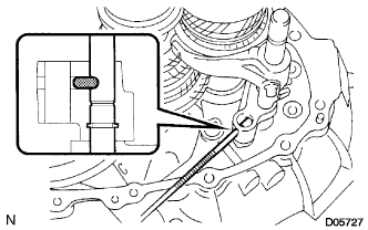
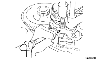
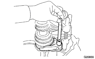
Using a pin punch and hammer, install the pinion shaft slotted spring pin through the front differential case and the hole in the pinion shaft.
-
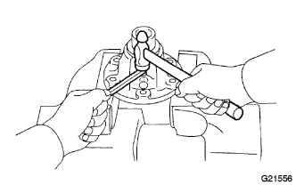
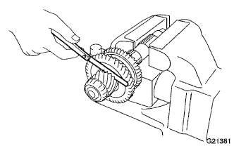
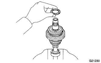
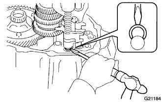
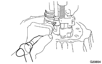
Using a hammer and chisel, caulk the pin holes around the circumference of the front differential case.
-
-
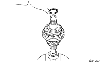
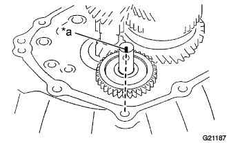
INSTALL FRONT DIFFERENTIAL RING GEAR
-
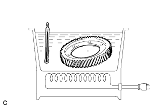
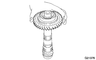
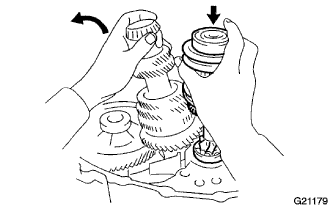
Using a heater, heat the front differential ring gear to 90 to 110°C (194.0 to 230.0°F).
-
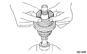
Clean the contact surface of the front differential case.
-
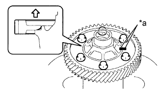
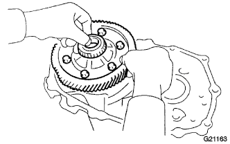
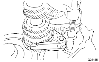
Text in Illustration *a Matchmark Align the matchmarks and quickly install the front differential ring gear onto the front differential case with the 6 bolts.
- Torque:
- 124 N*m { 1,260 kgf*cm, 91 ft.*lbf }
-
-
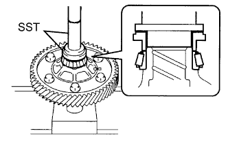
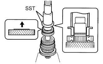
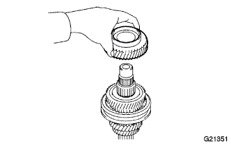
INSTALL FRONT DIFFERENTIAL CASE REAR TAPERED ROLLER BEARING
-
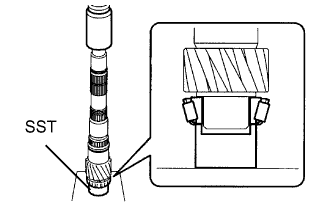
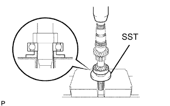
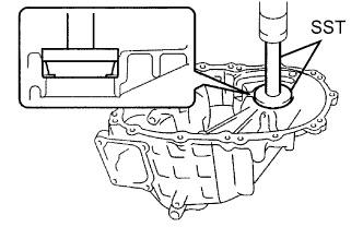
Using SST and a press, install the front differential case rear tapered roller bearing.
- SST
- 09350-32014 ( 09351-32120, 09351-32140 )
-
-
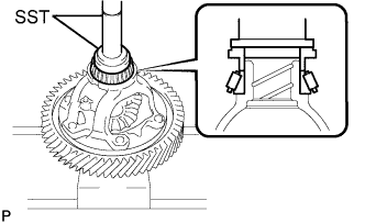
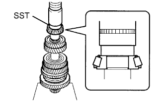
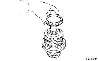
INSTALL FRONT DIFFERENTIAL CASE FRONT TAPERED ROLLER BEARING
-
Using SST and a press, install the front differential case front tapered roller bearing.
- SST
- 09350-32014 ( 09351-32120, 09351-32140 )
-
-
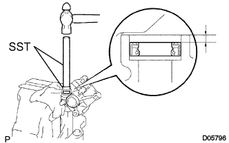
INSTALL CONTROL SHAFT COVER OIL SEAL
-
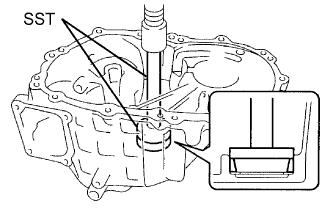
Using SST and a hammer, drive a new control shaft cover oil seal into the control shaft cover.
- SST
- 09950-60010 ( 09951-00220 )
- 09950-70010 ( 09951-07100 )
Drive in depth 2.0 to 2.5 mm (0.079 to 0.098 in.)
-
-
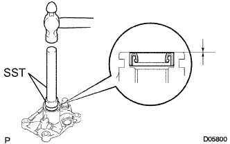
INSTALL SELECT LEVER SHAFT OIL SEAL
-
Using SST and a hammer, drive a new select lever shaft oil seal into the control shaft cover.
- SST
- 09950-60010 ( 09951-00280 )
- 09950-70010 ( 09951-07100 )
Drive in depth 0 to 0.5 mm (0 to 0.020 in.)
-
-
INSTALL SHIFT AND SELECT LEVER SHAFT
-
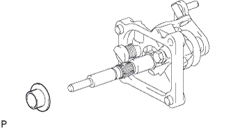
Install the spacer onto the shift and select lever shaft.
-
Install the shift lever boot onto the shift and select lever shaft.
-
Install the shift and select lever shaft with the shift lever boot onto the control shaft cover.
-
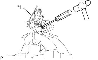
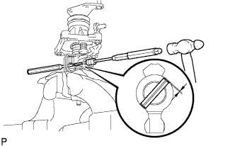
Text in Illustration *1 Rope Using a screwdriver and hammer, tap a new snap ring onto the shift and select lever shaft.
Tech Tips
Lift the control shaft cover up with a piece of rope or equivalent to make the work easier.
-
-
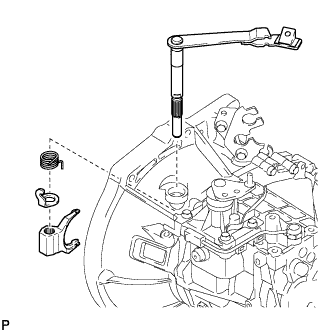
INSTALL SELECT INNER LEVER
-
Install the select inner lever onto the control shaft cover.
-
-
INSTALL SELECT LEVER SHAFT
-
Apply adhesive to the bolt threads.
Adhesive Toyota Genuine Adhesive 1344, Three Bond 1344 or equivalent -
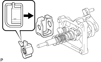
Install the select lever shaft onto the select inner lever and the control shaft cover with the bolt.
- Torque:
- 38 N*m { 387 kgf*cm, 28 ft.*lbf }
Note
Fit the edge of the select inner lever into the groove of the select lever shaft, as shown in the illustration.
-
-
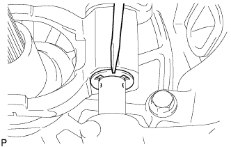
INSTALL SELECT SPRING SEAT NO. 2
-
Install select spring seat No. 2 onto the shift and select lever shaft.
-
-
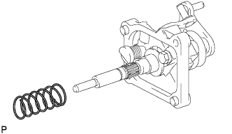
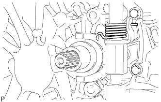
INSTALL SELECT RETURN COMPRESSION SPRING
-
Install the select return compression spring onto the shift and select lever shaft.
-
-
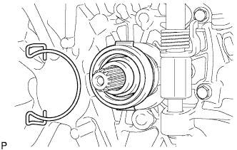
INSTALL SHIFT LEVER INNER NO. 1
-
Install shift lever inner No. 1 and the shift interlock plate onto the shift and select lever shaft.
-
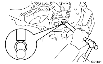
While pushing up shift lever inner No. 1 so that the hole in the inner lever is aligned with the hole in the shift and select lever shaft, insert a pin punch half way into the inner lever, and using another pin punch and a hammer, drive in the slotted spring pin.
When the No. 1 shift inner lever is fixed with the slotted spring pin, pull out the pin punch while holding the inner lever.
Drive in depth -0.5 to 0.5 mm (-0.020 to 0.020 in.) -
Using a screwdriver and hammer, tap a new snap ring onto the shift and select lever shaft.
-
-
INSTALL OUTPUT SHAFT FRONT BEARING
-
Using SST and a press, install the output shaft front bearing onto the output shaft.
- SST
- 09710-22021 ( 09710-01051 )
-
-
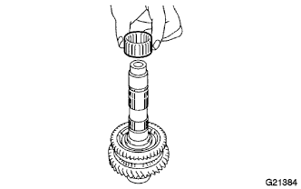
INSTALL 1ST GEAR NEEDLE ROLLER BEARING
-
Coat the 1st gear needle roller bearing with gear oil, and install it onto the output shaft.
-
-
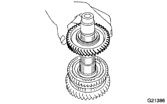
INSTALL 1ST GEAR
-
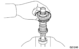
Coat the 1st gear with gear oil, and install it onto the output shaft.
-
-
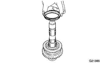
INSTALL 1ST GEAR SYNCHRONIZER RING
-
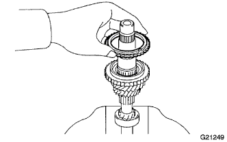
Coat the 1st gear synchronizer ring with gear oil, and install it onto the 1st gear.
-
-
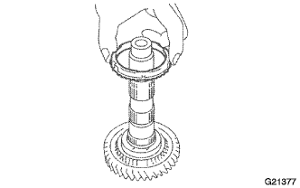
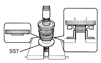
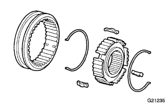
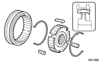
INSTALL TRANSMISSION CLUTCH HUB NO. 1
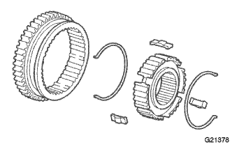
-
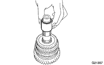
Install 2 No. 1 shifting key springs, 3 No. 1 shifting keys and the reverse gear onto transmission clutch hub No. 1.
-
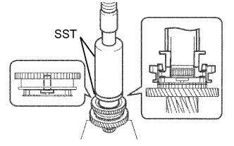
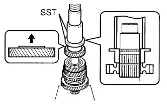
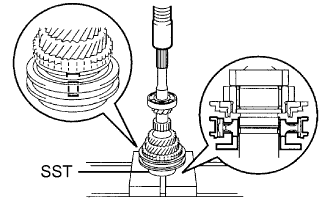
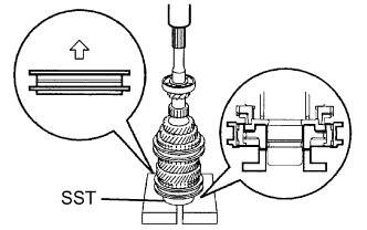
Using SST and a press, install transmission clutch hub No. 1 onto the output shaft.
- SST
- 09316-60011 ( 09316-00011, 09316-00071 )
Note
Install the reverse gear assembly in the correct orientation, as shown in the illustration.
-
-
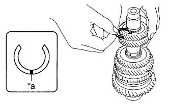
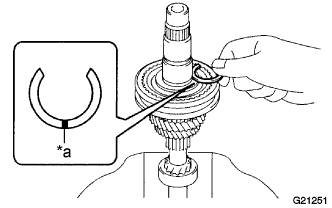
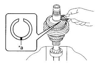
INSTALL CLUTCH HUB NO. 1 SHAFT SNAP RING
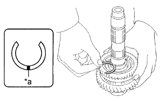
-
Select a snap ring that allows the minimum axial play.
Text in Illustration *a Mark Standard clearance 0 to 0.1 mm (0 to 0.0039 in.) Snap Ring Thickness Mark Thickness
mm (in.)
Mark Thickness
mm (in.)
A 2.28 (0.0898) D 2.46 (0.0969) B 2.34 (0.0921) E 2.52 (0.0992) C 2.40 (0.0945) F 2.58 (0.1016) -
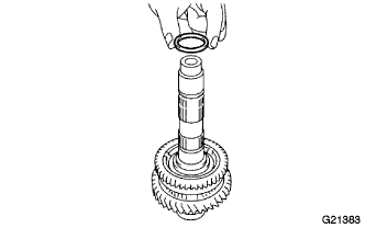
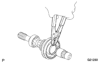
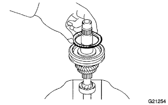
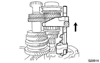
Using a snap ring expander, install a new snap ring onto the output shaft.
-
-
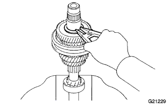
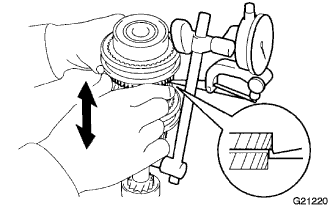
INSPECT 1ST GEAR THRUST CLEARANCE
-
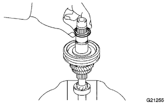
Using a feeler gauge, measure the 1st gear thrust clearance.
Standard clearance 0.10 to 0.35 mm (0.0039 to 0.0138 in.)
-
-
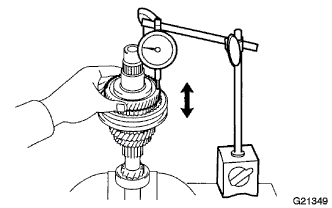
INSPECT 1ST GEAR RADIAL CLEARANCE
-
Using a dial indicator, measure the 1st gear radial clearance.
Standard clearance 0.015 to 0.056 mm (0.0006 to 0.0022 in.) Maximum clearance 0.056 mm (0.0022 in.) If the clearance exceeds the maximum, replace the 1st gear needle roller bearing.
-
-
INSTALL 2ND GEAR BEARING SPACER
-
Coat the 2nd gear bearing spacer with gear oil and install it onto the output shaft.
-
-
INSTALL 2ND GEAR NEEDLE ROLLER BEARING
-
Coat the 2nd gear needle roller bearing with gear oil, and install it onto the output shaft.
-
-
INSTALL 2ND GEAR SYNCHRONIZER RING
-
Coat the 2nd synchronizer ring with gear oil, and install it onto the reverse gear.
-
-
INSTALL 2ND GEAR
-
Coat the 2nd gear with gear oil, and install it onto the output shaft.
-
-
INSTALL 3RD DRIVEN GEAR
-
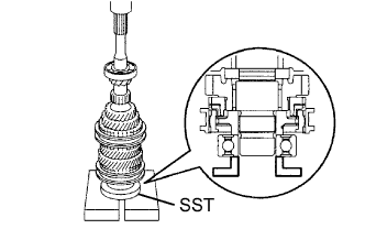
Using SST and a press, install the 3rd driven gear onto the output shaft.
- SST
- 09316-60011 ( 09316-00041 )
-
-
INSPECT 2ND GEAR THRUST CLEARANCE
-
Using a feeler gauge, measure the 2nd gear thrust clearance.
Standard clearance 0.10 to 0.55 mm (0.0039 to 0.0217 in.)
-
-
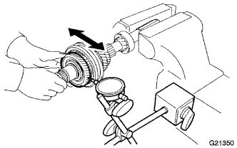
INSPECT 2ND GEAR RADIAL CLEARANCE
-
Using a dial indicator, measure the 2nd gear radial clearance between the gear and shaft.
Standard clearance 0.015 to 0.056 mm (0.0006 to 0.0023 in.) Maximum clearance 0.056 mm (0.0006 in.) If the clearance exceeds the maximum, replace the 2nd gear needle roller bearing.
-
-
INSTALL OUTPUT SHAFT SPACER
-
Install the output shaft spacer onto the output shaft.
-
-
INSTALL 4TH DRIVEN GEAR
-
Using SST and a press, install the 4th driven gear onto the output shaft.
- SST
- 09223-00010
- 09316-60011 ( 09316-00021 )
-
-
INSTALL 5TH DRIVEN GEAR
-
Using SST and a press, install the 5th driven gear onto the output shaft.
- SST
- 09223-00010
- 09316-60011 ( 09316-00021 )
-
-
INSTALL COUNTER 5TH GEAR SHAFT SNAP RING
-
Select a snap ring, using the table below, that makes the thrust clearance of the 5th driven gear less than 0.1 mm (0.0039 in.).
Text in Illustration *a Mark Snap Ring Thickness Mark Thickness
mm (in.)
Mark Thickness
mm (in.)
A 2.22 (0.0874) F 2.52 (0.0992) B 2.28 (0.0898) G 2.58 (0.1016) C 2.34 (0.0921) H 2.64 (0.1039) D 2.40 (0.0945) J 2.70 (0.1063) E 2.46 (0.0969) - - -
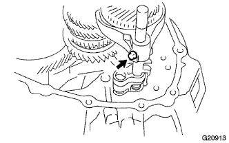
Using a brass bar and hammer, tap the new snap ring onto the output shaft.
-
-
INSTALL OUTPUT SHAFT REAR BEARING
-
Using SST and a press, install the output shaft rear bearing onto the output shaft.
- SST
- 09950-60010 ( 09951-00370 )
-
-
INSTALL INPUT SHAFT FRONT BEARING
-
Using SST and a press, install a new input shaft front bearing onto the input shaft.
- SST
- 09515-10010
-
-
INSTALL 3RD GEAR NEEDLE ROLLER BEARING
-
Coat the 3rd gear needle roller bearing with gear oil, and install it onto the input shaft.
-
-
INSTALL 3RD GEAR
-
Coat the 3rd gear with gear oil, and install it onto the input shaft.
-
-
INSTALL 3RD GEAR SYNCHRONIZER RING
-
Coat the 3rd gear synchronizer ring with gear oil, and install it onto the 3rd gear.
-
-
INSTALL TRANSMISSION CLUTCH HUB NO. 2
-
Install 3 No. 2 shifting keys, 2 No. 2 shifting key springs and transmission hub sleeve No. 2 onto clutch hub No. 2.
Note
Assemble transmission hub sleeve No. 2 and transmission clutch hub No. 2 in the correct orientations, as shown in the illustration.
-
Using SST and a press, install transmission clutch hub sleeve No. 2 onto the input shaft.
- SST
- 09506-35010
-
-
INSTALL CLUTCH HUB NO. 2 SETTING SHAFT SNAP RING
-
Select a snap ring that allows the minimum axial play.
Text in Illustration *a Mark Standard clearance 0.1 mm (0.0039 in.) or less. Snap Ring Thickness Mark Thickness
mm (in.)
Mark Thickness
mm (in.)
A 2.28 (0.0898) D 2.46 (0.0969) B 2.34 (0.0921) E 2.52 (0.0992) C 2.40 (0.0945) F 2.58 (0.1016) -
Using a snap ring expander, install a new snap ring onto the input shaft.
Note
Do not damage the journal surface of the input shaft.
-
-
INSPECT 3RD GEAR THRUST CLEARANCE
-
Using a feeler gauge, measure the 3rd gear thrust clearance.
Standard clearance 0.10 to 0.35 mm (0.0039 to 0.0138 in.)
-
-
INSPECT 3RD GEAR RADIAL CLEARANCE
-
Using a dial indicator, measure the 3rd gear radial clearance.
Standard clearance 0.015 to 0.058 mm (0.0006 to 0.0023 in.) If the clearance is outside the standard, replace the 3rd gear needle roller bearing.
-
-
INSTALL 4TH GEAR SYNCHRONIZER RING
-
Coat the 4th gear synchronizer ring with gear oil, and install it onto transmission clutch hub No. 2.
-
-
INSTALL 4TH GEAR BEARING SPACER
-
Coat the 4th gear bearing spacer with gear oil, and install it onto the input shaft.
-
-
INSTALL 4TH GEAR NEEDLE ROLLER BEARING
-
Coat the 4th gear needle roller bearing with gear oil, and install it onto the input shaft.
-
-
INSTALL 4TH GEAR
-
Coat the 4th gear with gear oil, and install it onto the input shaft.
-
-
INSTALL 5TH GEAR THRUST WASHER BALL
-
Install the 5th gear thrust washer ball onto the input shaft.
-
-
INSTALL 5TH GEAR THRUST WASHER
-
Coat the 5th gear thrust washer with gear oil, and install it onto the input shaft.
-
-
INSTALL 5TH GEAR SHAFT SNAP RING
-
Select a snap ring, using the table below, that makes the thrust clearance of the 5th gear thrust washer less than 0.1 mm (0.0039 in.).
Text in Illustration *a Mark Snap Ring Thickness Mark Thickness
mm (in.)
Mark Thickness
mm (in.)
1 2.28 (0.0898) 4 2.46 (0.0969) 2 2.34 (0.0921) 5 2.52 (0.0992) 3 2.40 (0.0945) 6 2.58 (0.1016) -
Using a snap ring expander, install a new snap ring onto the input shaft.
Note
Do not damage the journal surface of the input shaft.
-
-
INSPECT 4TH GEAR THRUST CLEARANCE
-
Using a dial indicator, measure the 4th gear thrust clearance.
Standard clearance 0.1 to 0.55 mm (0.0039 to 0.0217 in.)
-
-
INSPECT 4TH GEAR RADIAL CLEARANCE
-
Using a dial indicator, measure the 4th gear radial clearance.
Standard clearance 0.015 to 0.058 mm (0.0006 to 0.0023 in.) Maximum clearance 0.058 mm (0.0023 in.) If the clearance exceeds the maximum, replace the 4th gear needle roller bearing or the shaft.
-
-
INSTALL 5TH GEAR BEARING SPACER
-
Coat the 5th gear bearing spacer with gear oil, and install it onto the input shaft.
-
-
INSTALL 5TH GEAR NEEDLE ROLLER BEARING
-
Coat the 5th gear needle roller bearing with gear oil, and install it onto the input shaft.
-
-
INSTALL 5TH GEAR
-
Coat the 5th gear with gear oil, and install it onto the input shaft.
-
-
INSTALL 5TH GEAR SYNCHRONIZER RING
-
Coat the 5th gear synchronizer ring with gear oil, and install it onto the 5th gear.
-
-
INSTALL TRANSMISSION CLUTCH HUB NO. 3
-
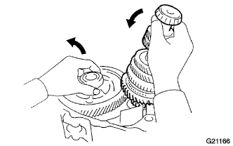
Install the 3 No. 3 shifting keys, 2 No. 3 shifting key springs and transmission hub sleeve No. 3 onto transmission clutch hub No. 3.
Note
Assemble transmission hub sleeve No. 3 and transmission clutch hub No. 3 in the correct orientations, as shown in the illustration.
-
Place the 5th gear synchronizer ring on the 5th gear, and align the synchronizer ring slots with shifting keys No. 3.
-
Using SST and a press, press No. 3 hub sleeve into the input shaft.
- SST
- 09515-10010
Note
Install transmission hub sleeve No. 3 in the correct orientation, as shown in the illustration.
-
-
INSTALL INPUT SHAFT REAR RADIAL BALL BEARING
-
Using SST and a press, install a new input shaft rear radial ball bearing onto the input shaft.
- SST
- 09515-10010
-
-
INSPECT 5TH GEAR THRUST CLEARANCE
-
Using a dial indicator, measure the 5th gear thrust clearance.
Standard clearance 0.10 to 0.50 mm (0.0039 to 0.0197 in.) Maximum clearance 0.50 mm (0.0197 in.)
-
-
INSPECT 5TH GEAR RADIAL CLEARANCE
-
Using a dial indicator, measure the 5th gear radial clearance.
Standard clearance 0.015 to 0.058 mm (0.0006 to 0.0023 in.) Maximum clearance 0.058 mm (0.0023 in.) If the clearance exceeds the maximum, replace the 5th gear needle roller bearing.
-
-
INSTALL OUTPUT SHAFT COVER
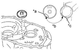
Text in Illustration *a Hole *b Align *c Groove
-
Install the output shaft cover, as shown in the illustration.
-
-
INSTALL OUTPUT SHAFT FRONT BEARING
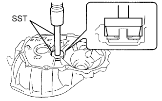
-
Using SST and a press, press in the output shaft front bearing (outer race).
- SST
- 09950-60010 ( 09951-00510 )
- 09950-70010 ( 09951-07150 )
-
-
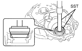
INSTALL FRONT DIFFERENTIAL CASE FRONT TAPERED ROLLER BEARING
-
Using SST and a press, press in the front differential case front tapered roller bearing (outer race).
- SST
- 09350-32014 ( 09351-32111, 09351-32130 )
-
-
INSTALL FRONT DIFFERENTIAL CASE REAR TAPERED ROLLER BEARING
-
Install the shim onto the manual transmission case.
Tech Tips
When reusing the output shaft rear tapered roller bearing, first install a shim of the same thickness as before.
When installing a new output shaft rear tapered roller bearing, first select and install a shim which is thinner than the original.
-
Using SST and a press, press in the front differential case rear tapered roller bearing (outer race).
- SST
- 09950-60010 ( 09951-00620 )
- 09950-70010 ( 09951-07100 )
-
-
ADJUST DIFFERENTIAL SIDE BEARING PRELOAD
-
Coat the differential case with gear oil, and install it onto the front transaxle case.
-
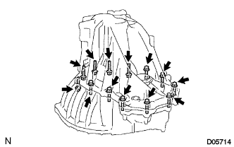
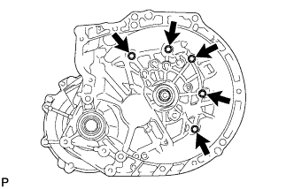
Install the manual transmission case with the 13 bolts.
- Torque:
- 29 N*m { 300 kgf*cm, 22 ft.*lbf }
Tech Tips
Manual transmission case side: 8 bolts
Front transaxle case side: 5 bolts
-
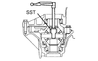
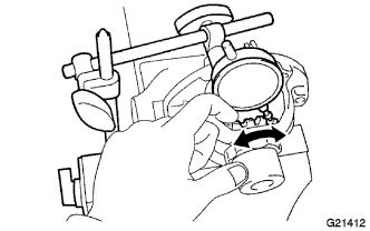
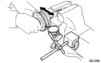
Using SST and a torque wrench, turn the differential case right and left 2 or 3 times to allow the bearings to settle.
- SST
- 09564-32011
-
Using SST and a torque wrench, measure the starting preload.
- SST
- 09564-32011
New bearing preload 0.78 to 1.57 N*m (7.95 to 16.00 kgf*cm, 6.9 to 13.89 in.*lbf) Used bearing preload 0.49 to 0.98 N*m (5.00 to 9.99 kgf*cm, 4.3 to 8.67 in.*lbf) -
Select a new shim.
Differential Case Shim Thickness Mark Thickness
mm (in.)
Mark Thickness
mm (in.)
Mark Thickness
mm (in.)
01 1.10 (0.0433) 08 1.45 (0.0571) 15 1.80 (0.0709) 02 1.15 (0.0453) 09 1.50 (0.0591) 16 1.85 (0.0728) 03 1.20 (0.0472) 10 1.55 (0.0610) 17 1.90 (0.0748) 04 1.25 (0.0492) 11 1.60 (0.0630) 18 1.95 (0.0768) 05 1.30 (0.0512) 12 1.65 (0.0650) 19 2.00 (0.0787) 06 1.35 (0.0531) 13 1.70 (0.0669) - - 07 1.40 (0.0551) 14 1.75 (0.0689) - - -
Remove the 13 bolts and the manual transmission case from the front transaxle case.
-
Remove the differential case from the front transaxle case.
-
-
INSTALL OUTPUT SHAFT REAR BEARING
-
Install the output shaft rear bearing shim onto the manual transmission case.
Tech Tips
When reusing the output shaft rear tapered roller bearing, first install a shim of the same thickness as before.
When installing a new output shaft rear tapered roller bearing, first select and install a shim which is thinner than the original.
-
Using SST and a press, press in the output shaft rear bearing (outer race).
- SST
- 09950-60010 ( 09951-00570 )
- 09950-70010 ( 09951-07200 )
-
-
ADJUST OUTPUT SHAFT BEARING PRELOAD
-
Install the output shaft assembly and the differential case onto the front transaxle case.
-
Install the manual transmission case onto the front transaxle case with the 13 bolts.
- Torque:
- 29 N*m { 300 kgf*cm, 22 ft.*lbf }
Tech Tips
Manual transmission case side: 8 bolts
Front transaxle case side: 5 bolts
-
Using SST and a torque wrench, turn the output shaft assembly and the differential case right and left 2 or 3 times to allow the bearings to settle.
- SST
- 09564-32011
-
Using SST and a torque wrench, measure the starting preload.
New bearing preload 2.79 to 5.56 N*m (28.4 to 56.7 kgf*cm, 24.7 to 49.2 in.*lbf) Used bearing preload 1.73 to 3.47 N*m (17.6 to 35.4 kgf*cm, 15.3 to 30.7 in.*lbf) -
Select a new output shaft rear bearing shim.
Output Shaft Rear Bearing Shim Thickness Mark Thickness
mm (in.)
Mark Thickness
mm (in.)
A 1.55 (0.0610) J 1.95 (0.0768) B 1.60 (0.0630) K 2.00 (0.0787) C 1.65 (0.0650) L 2.05 (0.0807) D 1.70 (0.0669) M 2.10 (0.0827) E 1.75 (0.0689) N 2.15 (0.0846) F 1.80 (0.0709) P 2.20 (0.0866) G 1.85 (0.0728) Q 2.25 (0.0886) H 1.90 (0.0748) - - -
Remove the 13 bolts and the manual transmission case from the front transaxle case.
-
Remove the output shaft assembly from the front transaxle case.
-
Remove the differential case from the front transaxle case.
-
-
ADJUST INPUT SHAFT REAR BEARING SHIM
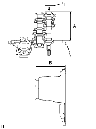
Text in Illustration *1 Input Shaft Rear Bearing Shim
-
Using vernier calipers, accurately measure dimensions A and B.
-
Select an input shaft rear bearing shim that brings the value to within the specifications.
Standard Shim thickness (B - A) should be more than 0 mm (0 in.) and less than 0.1 mm (0.0039 in.) Input Shaft Rear Bearing Shim Thickness Mark Thickness
mm (in.)
Mark Thickness
mm (in.)
F 1.80 (0.0709) N 2.15 (0.0846) G 1.85 (0.0728) P 2.20 (0.0866) H 1.90 (0.0748) Q 2.25 (0.0886) J 1.95 (0.0768) R 2.30 (0.0906) K 2.00 (0.0787) S 2.35 (0.0925) L 2.05 (0.0807) T 2.40 (0.0945) M 2.10 (0.0827) - - -
Install the input shaft rear bearing shim.
-
-
INSTALL TRANSMISSION CASE OIL SEAL
-
INSTALL TRANSAXLE CASE OIL SEAL
-
INSTALL FRONT TRANSAXLE CASE OIL SEAL
-
Using SST and a hammer, install a new front transaxle case oil seal into the front transaxle case.
- SST
- 09710-20011 ( 09710-06071 )
- 09950-70010 ( 09951-07150 )
Drive in depth 14.4 to 15.4 mm (0.567 to 0.606 in.) -
Coat the tip of the front transaxle case oil seal with MP grease.
-
-
INSTALL TRANSMISSION MAGNET
-
Clean and reinstall the transmission magnet onto the front transaxle case.
-
-
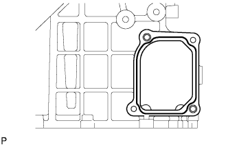
INSTALL OIL RECEIVER PIPE NO. 2
-
Install oil receiver pipe No. 2 onto the manual transmission case.
Note
Do not damage oil receiver pipe No. 2.
-
-
INSTALL DIFFERENTIAL CASE ASSEMBLY
-
Coat the differential case tapered roller bearing with gear oil, and install it onto the front transaxle case.
-
-
INSTALL OUTPUT SHAFT ASSEMBLY
-
Install the output shaft assembly onto the front transaxle case.
-
-
INSTALL INPUT SHAFT ASSEMBLY
-
Coat sliding and rotating surfaces of the input assembly and output shaft assembly with gear oil, and install them onto the front transaxle case.
-
-
INSTALL GEAR SHIFT FORK SHAFT NO. 2
-
Install gear shift fork No. 2 onto gear shift fork shaft No. 2.
-
Using a hammer, tap a new snap ring onto gear shift fork shaft No. 2.
-
Install the reverse shift fork onto gear shift fork shaft No. 2.
-
Shift gear shift fork No. 2 to the 4th gear.
-
Install gear shift fork shaft No. 2, gear shift fork No. 2 and the reverse shift fork.
-
Coat gear shift fork No. 2 bolt with adhesive.
Adhesive Toyota Genuine Adhesive 1324, Three Bond 1324 or equivalent -
Install gear shift fork No. 2 bolt onto gear shift fork No. 2.
- Torque:
- 16 N*m { 160 kgf*cm, 12 ft.*lbf }
-
Using a brass bar and hammer, install a new snap ring onto gear shift fork shaft No. 2.
-
Using a magnetic finger, install the straight pin onto the reverse shift fork.
-
-
INSTALL GEAR SHIFT FORK SHAFT NO. 3
-
Install gear shift fork No. 3 onto hub sleeve No. 3.
-
Using a hammer, tap a new snap ring onto gear shift fork shaft No. 3.
-
Install gear shift fork shaft No. 3, the compression spring, gear shift head No. 3 and gear shift fork No. 3 onto the front transaxle case.
-
Using a pin punch and hammer, drive the slotted spring pin into gear shift head No. 3.
-
Using a screwdriver and hammer, tap a new snap ring onto gear shift fork shaft No. 3.
-
Install the straight pin onto gear shift fork No. 3.
-
-
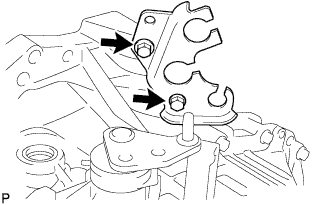
INSTALL GEAR SHIFT FORK SHAFT NO. 1
-
Install gear shift fork No. 1 onto hub sleeve No. 1.
-
Using a hammer, tap a new snap ring onto gear shift fork shaft No. 1.
-
Install gear shift fork shaft No. 1, gear shift head No. 1 and gear shift fork No. 1.
-
Using a pin punch and hammer, drive the slotted spring pin into gear shift head No. 1.
-
Coat gear shift fork No. 1 bolt with adhesive.
Adhesive Toyota Genuine Adhesive 1324, Three Bond 1324 or equivalent -
Install the bolt onto gear shift fork No. 1.
- Torque:
- 16 N*m { 160 kgf*cm, 12 ft.*lbf }
-
-
INSTALL REVERSE IDLER GEAR SUB-ASSEMBLY
-
INSTALL REVERSE IDLER GEAR SHAFT
-
Coat the reverse idler gear shaft with gear oil, and install it as shown.
-
Text in Illustration *a Mark Align the mark on the reverse idler gear shaft with the bolt hole, as shown in the illustration.
-
-
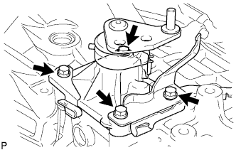
INSTALL REVERSE SHIFT ARM BRACKET ASSEMBLY
-
Install the reverse shift arm bracket assembly onto the front transaxle case with the 2 bolts.
- Torque:
- 17 N*m { 175 kgf*cm, 13 ft.*lbf }
-
-
INSTALL MANUAL TRANSMISSION CASE
-
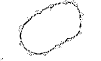
Apply seal packing to the manual transmission case, as shown in the illustration.
Seal packing Toyota Genuine Seal Packing 1281, Three Bond 1281 or equivalent Note
Assemble parts within 10 minutes of application. Otherwise, the packing material must be removed and reapplied.
-
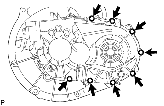
Install the 8 bolts onto the manual transmission side.
- Torque:
- 29 N*m { 300 kgf*cm, 22 ft.*lbf }
-
Install the 5 bolts onto the manual transaxle side.
- Torque:
- 29 N*m { 300 kgf*cm, 22 ft.*lbf }
-
-
INSTALL REVERSE IDLER GEAR SHAFT BOLT
-
Coat the reverse idler gear shaft bolt with adhesive, and install it with a new gasket.
Adhesive Toyota Genuine Adhesive 1324, Three Bond 1324 or equivalent - Torque:
- 29 N*m { 300 kgf*cm, 22 ft.*lbf }
-
-
INSTALL SHIFT AND SELECT LEVER SHAFT ASSEMBLY
-
Install the select return compression spring onto the manual transmission case.
-
Apply seal packing to the manual transmission case, as shown in the illustration.
Seal packing Toyota Genuine Seal Packing 1281, Three Bond 1281 or equivalent -
Coat the 4 bolts with adhesive.
Adhesive Toyota Genuine Adhesive 1344, Three Bond 1344 or equivalent -
Install the shift and select lever shaft, wire harness clamp bracket and release fork retracting spring hanger onto the manual transmission case with the 4 bolts.
- Torque:
- 18 N*m { 184 kgf*cm, 13 ft.*lbf }
-
-
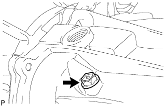
INSTALL LOCK BALL ASSEMBLY NO. 1
-
Coat lock ball No. 1 with adhesive.
Adhesive Toyota Genuine Adhesive 1344, Three Bond 1344 or equivalent -
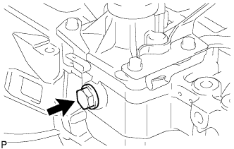
Install lock ball No. 1 onto the manual transmission case.
- Torque:
- 37 N*m { 375 kgf*cm, 27 ft.*lbf }
-
-
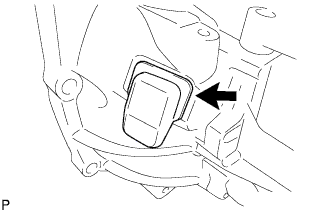
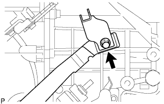
INSTALL BACK-UP LIGHT SWITCH ASSEMBLY
-
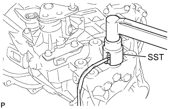
Using SST, install the back-up light switch with a new gasket onto the manual transmission case.
- SST
- 09817-16011
- Torque:
- 40 N*m { 410 kgf*cm, 30 ft.*lbf }
-
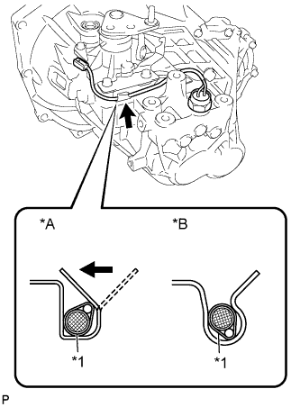
Text in Illustration *A for Bend Type *B for Clamp Type *1 Wire Harness Install the back-up light switch wire harness into the clamp bracket.
Tech Tips
-
For bend type :
Fit the wire harness into the bracket and push it closed with your finger.
-
For clamp type :
Insert the wire harness into the clamp of the bracket.
-
-
-
INSTALL MANUAL TRANSAXLE CASE PLUG
-
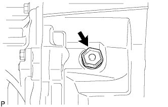
Install the manual transaxle case plug with a new gasket.
- Torque:
- 39 N*m { 400 kgf*cm, 29 ft.*lbf }
-
-
INSTALL FLOOR SHIFT CONTROL LEVER HOUSING SUPPORT BRACKET
-
Install the floor shift control lever housing support bracket onto the manual transaxle case with the 2 bolts.
- Torque:
- 11 N*m { 115 kgf*cm, 8.3 ft.*lbf }
-
-
INSTALL CLUTCH HOUSING COVER NO. 1
-
Install clutch housing cover No. 1 onto the manual transaxle case.
-
-
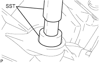
INSTALL CLUTCH RELEASE FORK LEVER SHAFT OIL SEAL
-
Using SST and a hammer, tap in a new select lever shaft oil seal until its surface is flush with the manual transaxle case.
-
-
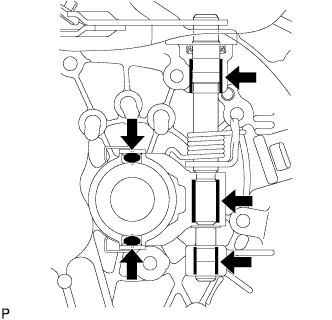
INSTALL CLUTCH RELEASE FORK LEVER
-
Apply clutch release grease to the contact surface between the release bearing and the release fork, the rotating and sliding parts of the release lever and the spline coupling part.
Note
Apply grease uniformly to the rotating and sliding parts of the release lever and spline coupling part.
Remove any grease extending beyond the release lever joining part.
-
Install the release fork lever onto the transaxle case together with the torsion spring, spring stopper and the release fork.
-
Using a screwdriver and hammer, install a new E-ring.
-
Secure the torsion spring to the release fork.
Note
Hold the spring and spring stopper up to the upper end of the release fork lever first, and then secure the spring.
-
-
INSTALL CLUTCH RELEASE BEARING ASSEMBLY
-
Install the release bearing onto the transaxle case.
-
-
INSTALL RELEASE FORK RETRACTING SPRING HANGER
-
Install the release fork retracting spring hanger onto the release fork lever with the bolt.
- Torque:
- 33 N*m { 336 kgf*cm, 24 ft.*lbf }
-