MANUAL TRANSAXLE ASSEMBLY DISASSEMBLY

-
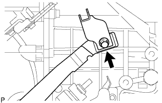
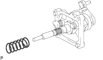
REMOVE RELEASE FORK RETRACTING SPRING HANGER
-
Remove the bolt and the release fork retracting spring hanger.
-
-
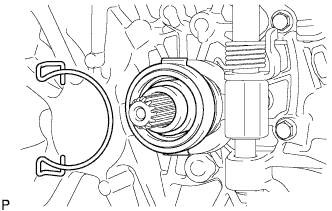
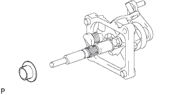
REMOVE CLUTCH RELEASE BEARING ASSEMBLY
-
Remove the clutch release bearing from the clutch release fork.
-
-
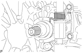
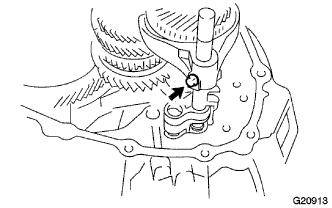
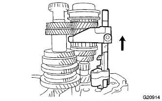
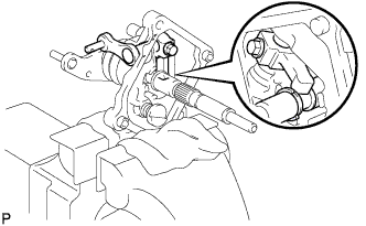
REMOVE CLUTCH RELEASE FORK LEVER
-
Separate the torsion spring from the clutch release fork.
-
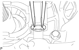
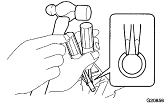
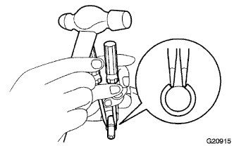
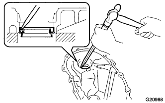
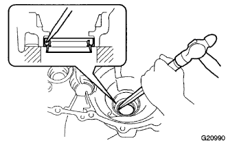
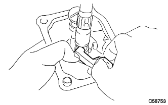
Using 2 screwdrivers and a hammer, tap the E-ring off.
-
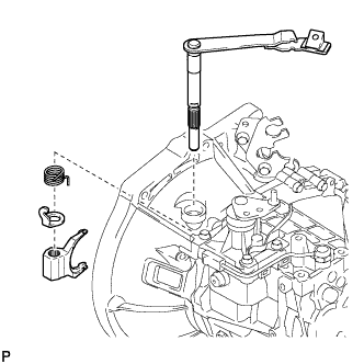
Pull the clutch release fork lever out of the transaxle case to remove the clutch release fork, and then release the fork torsion spring stopper and torsion spring from the clutch.
-
-
REMOVE CLUTCH RELEASE FORK LEVER SHAFT OIL SEAL
-
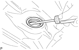
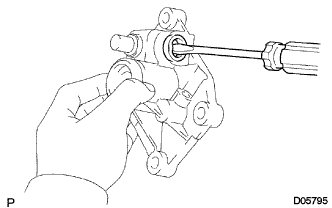
Using a screwdriver, remove the clutch release fork lever oil seal.
-
-
REMOVE CLUTCH HOUSING COVER NO.1
-
Remove the clutch housing cover from the transaxle case.
-
-
REMOVE FLOOR SHIFT CONTROL LEVER HOUSING SUPPORT BRACKET
-
Remove the 2 bolts and cable control bracket from the transaxle case.
-
-
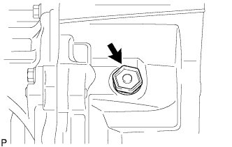
REMOVE MANUAL TRANSAXLE CASE PLUG
-
Remove the manual transaxle case plug and gasket from the manual transaxle case.
-
-
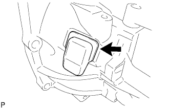
REMOVE BACK-UP LIGHT SWITCH ASSEMBLY
-
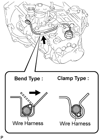
Separate the back-up light switch wire harness from the clamp bracket.
Tech Tips
-
For bend type :
Expand the clamp with your finger and separate the harness from the bracket.
-
For clamp type :
Pull the wire harness out and separate it from the bracket.
-
-
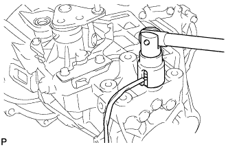
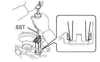
Using SST, remove the back-up light switch and gasket from the manual transmission case.
- SST
- 09817-16011
-
-
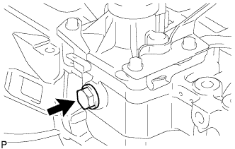
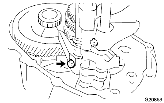
REMOVE LOCK BALL ASSEMBLY NO. 1
-
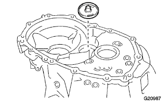
Remove lock ball No. 1 from the manual transmission case.
-
-
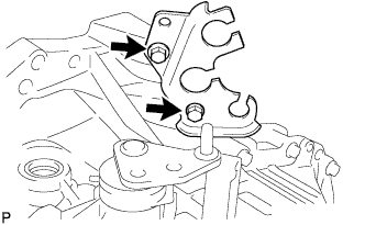
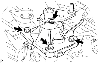
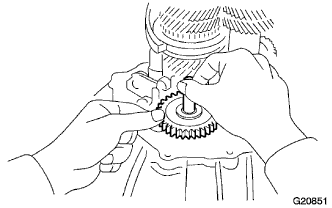
REMOVE SHIFT AND SELECT LEVER SHAFT ASSEMBLY
-
Remove the 4 bolts and shift and select lever shaft from the transmission case.
-
Remove the select return compression spring from the transmission case.
-
-
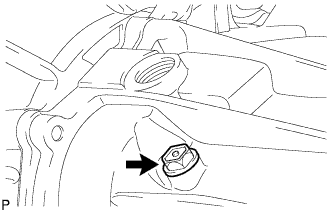
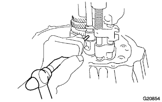
REMOVE REVERSE IDLER GEAR SHAFT BOLT
-
Remove the reverse idler gear shaft bolt and gasket.
-
-
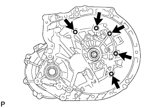
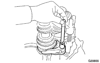
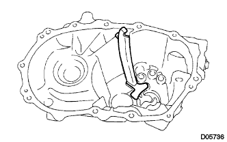
REMOVE MANUAL TRANSMISSION CASE
-
Remove the 5 bolts from the manual transaxle case side.
-
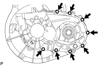
Remove the 8 bolts from the manual transmission case side.
-
Using a plastic hammer, remove the manual transmission case.
-
-
REMOVE REVERSE IDLER GEAR SHAFT
-
Remove the reverse idler gear shaft from the transaxle case.
-
-
REMOVE REVERSE IDLER GEAR SUB-ASSEMBLY
-
Remove the reverse idler gear from the transaxle case.
-
-
REMOVE REVERSE SHIFT ARM BRACKET ASSEMBLY

-
Remove the 2 bolts and the reverse shift arm bracket from the front transaxle case.
-
-
REMOVE GEAR SHIFT FORK SHAFT NO. 1
-
Remove the bolt from gear shift fork No. 1.
-
Using a pin punch and hammer, remove the slotted spring pin from gear shift head No. 1.
-
Remove gear shift fork shaft No. 1, gear shift head No. 1 and gear shift fork No. 1.
-
Using 2 screwdrivers and a hammer, remove the snap ring from gear shift fork shaft No. 1.
-
-
REMOVE GEAR SHIFT FORK SHAFT NO. 3
-
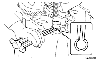
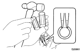
Remove the straight pin from gear shift fork No. 3.
-
Using a pin punch and hammer, remove the slotted spring pin from gear shift head No. 3.
-
Using 2 screwdrivers and a hammer, remove the snap ring from gear shift fork shaft No. 3.
Tech Tips
Use a shop rag or piece of cloth to prevent the snap ring from flying off.
-
Remove gear shift fork shaft No. 3, compression spring, gear shift head No. 3 and gear shift fork No. 3 from the front transaxle case.
-
Using 2 screwdrivers and a hammer, remove the snap ring from gear shift fork shaft No. 3.
Tech Tips
Use a shop rag or piece of cloth to prevent the snap ring from flying off.
-
-
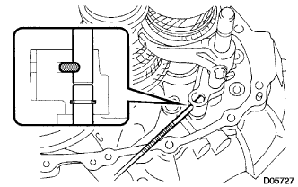
REMOVE GEAR SHIFT FORK SHAFT NO. 2
-
Using a magnetic finger, remove the straight pin from the reverse shift fork.
-
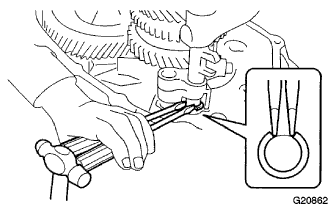
Using 2 screwdrivers and a hammer, remove the snap ring from gear shift fork shaft No. 3.
Tech Tips
Use a shop rag or piece of cloth to prevent the snap ring from flying off.
-
Remove the bolt from gear shift fork No. 2.
-
Shift gear shift fork No. 2 to the 4th gear range.
-
Remove gear shift fork shaft No. 2, gear shift fork No. 2 and reverse shift fork.
-
Using 2 screwdrivers and a hammer, remove the snap ring from gear shift fork shaft No. 2.
Tech Tips
Use a shop rag or piece of cloth to prevent the snap ring from flying off.
-
-
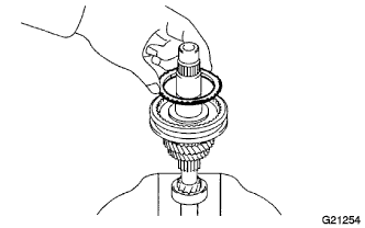
REMOVE INPUT SHAFT ASSEMBLY
-
Remove the input shaft assembly from the manual transaxle case.
-
-
REMOVE OUTPUT SHAFT ASSEMBLY
-
Remove the output shaft assembly from the manual transaxle case.
-
-
REMOVE DIFFERENTIAL CASE ASSEMBLY
-
Remove the differential case assembly from the front transaxle case.
-
-
REMOVE OIL RECEIVER PIPE NO. 2
-
Remove oil receiver pipe No. 2 from the manual transmission case.
Note
Do not damage oil receiver pipe No. 2.
-
-
REMOVE TRANSMISSION MAGNET
-
Remove the transmission magnet from the front transaxle case.
-
-
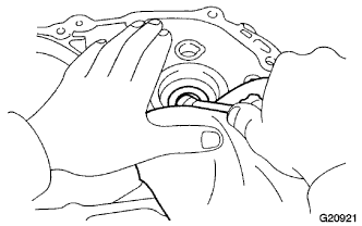
REMOVE FRONT TRANSAXLE CASE OIL SEAL
-
Using a screwdriver, remove the front transaxle case oil seal.
-
-
REMOVE OUTPUT SHAFT FRONT BEARING
-
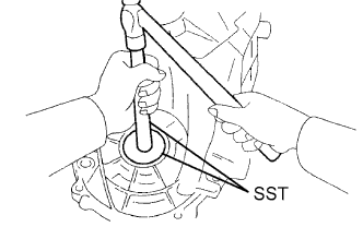
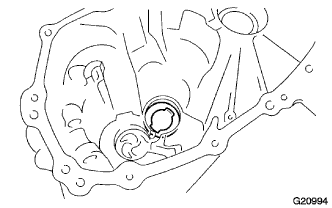
Using SST, remove the output shaft front bearing (outer race) from the front transaxle case.
- SST
- 09308-00010
-
-
REMOVE OUTPUT SHAFT COVER
-
Remove the output shaft cover from the transaxle case.
-
-
REMOVE TRANSMISSION CASE OIL SEAL
-
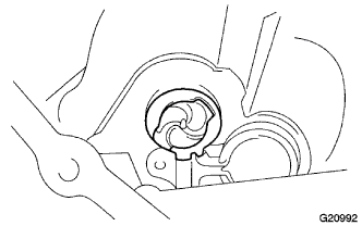
Using a screwdriver, remove the transmission case oil seal.
-
-
REMOVE FRONT DIFFERENTIAL CASE REAR TAPERED ROLLER BEARING
-
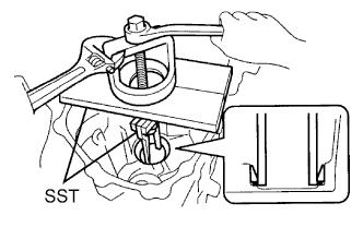
Using SST, remove the front differential case rear tapered roller bearing and the shim.
- SST
- 09950-60010 ( 09951-00560 )
- 09950-70010 ( 09951-07200 )
-
-
REMOVE TRANSAXLE CASE OIL SEAL
-
Using a screwdriver, remove the transaxle case oil seal from the transaxle case.
-
-
REMOVE FRONT DIFFERENTIAL CASE FRONT TAPERED ROLLER BEARING
-
Using SST, remove the front differential case front tapered roller bearing.
- SST
- 09387-00041 ( 09387-02010, 09387-02020 )
-
-
REMOVE INPUT SHAFT REAR BEARING SHIM
-
Remove the input shaft rear bearing shim from the transmission case.
-
-
REMOVE OUTPUT SHAFT REAR BEARING
-
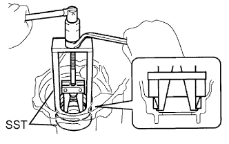
Using SST, remove the output shaft rear bearing.
- SST
- 09527-30010
- 09612-65014 ( 09612-01030, 09612-01050 )
-
-
REMOVE OUTPUT SHAFT REAR BEARING SHIM
-
Remove the output shaft rear bearing shim.
-
-
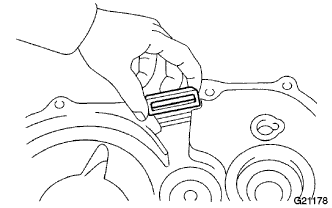
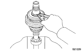
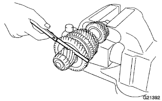
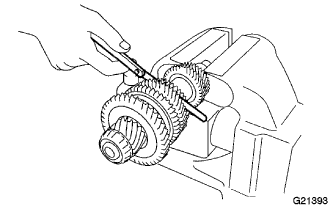
INSPECT 3RD GEAR THRUST CLEARANCE
-
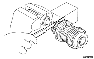
Using a feeler gauge, measure the 3rd gear thrust clearance.
Standard clearance 0.10 to 0.35 mm (0.0039 to 0.0138 in.) Maximum clearance 0.35 mm (0.0138 in.)
-
-
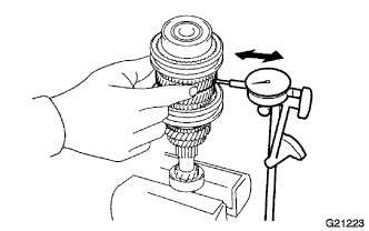
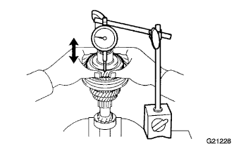
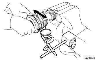
INSPECT 5TH GEAR THRUST CLEARANCE
-
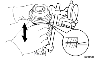
Using a dial indicator, measure the 5th gear thrust clearance.
Standard clearance 0.10 to 0.50 mm (0.0039 to 0.0197 in.) Maximum clearance 0.50 mm (0.0197 in.)
-
-
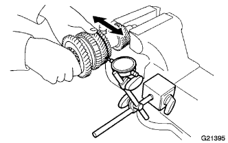
INSPECT 3RD GEAR RADIAL CLEARANCE

-
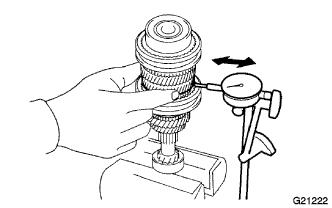
Using a dial indicator, measure the 3rd gear radial clearance.
Standard clearance 0.015 to 0.058 mm (0.0006 to 0.0023 in.) Maximum clearance 0.058 mm (0.0023 in.) If the clearance exceeds the maximum, replace the 3rd gear needle roller bearing or the shaft.
-
-
INSPECT 4TH GEAR RADIAL CLEARANCE
-
Using a dial indicator, measure the 4th gear radial clearance.
Standard clearance 0.015 to 0.058 mm (0.0006 to 0.0023 in.) Maximum clearance 0.058 mm (0.0023 in.) If the clearance exceeds the maximum, replace the 4th gear needle roller bearing or the shaft.
-
-
INSPECT 5TH GEAR RADIAL CLEARANCE
-
Using a dial indicator, measure the 5th gear radial clearance.
Standard clearance 0.015 to 0.058 mm (0.0006 to 0.0023 in.) Maximum clearance 0.058 mm (0.0023 in.) If the clearance exceeds the maximum, replace the 5th gear needle roller bearing or the shaft.
-
-
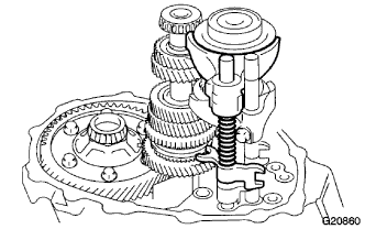
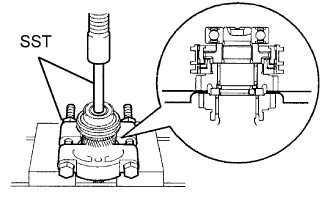
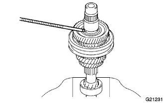
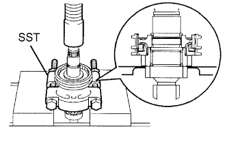
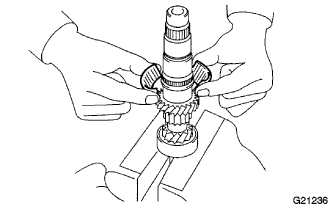
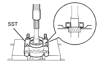
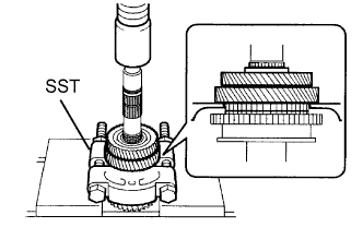
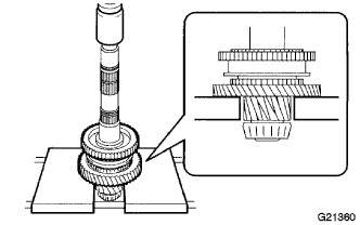
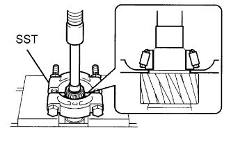
REMOVE 5TH GEAR
-
Using SST and a press, remove the input shaft rear radial ball bearing, hub sleeve No. 3, 5th gear synchronizer ring and 5th gear from the input shaft.
- SST
- 09950-00020
- 09612-24014 ( 09612-10061 )
Tech Tips
-
Support the input shaft by hand to prevent it from dropping off.
-
Set the claw of SST between the 4th gear and 5th gear, as shown in the illustration.
Note
Do not excessively tighten SST.
-
-
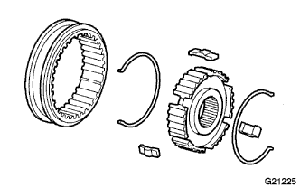
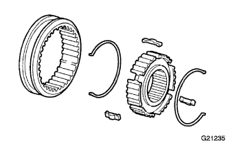
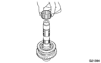
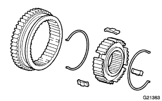
REMOVE TRANSMISSION CLUTCH HUB NO. 3
-
Remove the 2 No. 3 shifting key springs from transmission clutch hub No. 3.
-
Remove transmission hub sleeve No. 3 from transmission clutch hub No. 3.
-
Remove the 3 No.3 shifting keys from transmission clutch hub No. 3.
-
-
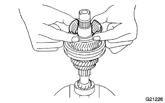
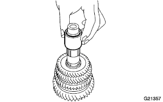
REMOVE 5TH GEAR NEEDLE ROLLER BEARING
-
Remove the 5th gear needle roller bearing from the input shaft.
-
-
REMOVE 5TH GEAR BEARING SPACER
-
Remove the 5th gear bearing spacer from the input shaft.
-
-
INSPECT 4TH GEAR THRUST CLEARANCE
-
Using a dial indicator, measure the 4th gear thrust clearance.
Standard clearance 0.10 to 0.55 mm (0.0039 to 0.0217 in.) Maximum clearance 0.55 mm (0.0217 in.)
-
-
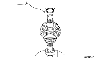
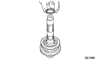
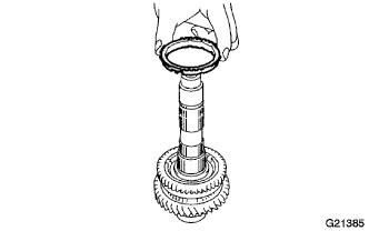
REMOVE 5TH GEAR SHAFT SNAP RING
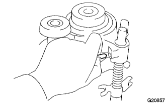
-
Using a snap ring expander, remove the 5th gear shaft snap ring from the input shaft.
Tech Tips
Do not damage the journal surface of the input shaft.
-
-
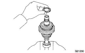
REMOVE 5TH GEAR THRUST WASHER
-
Remove the 5th gear thrust washer from the input shaft.
-
-
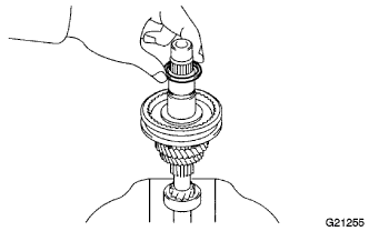
REMOVE 5TH GEAR THRUST WASHER BALL
-
Using a magnetic finger, remove the ball from the input shaft.
-
-
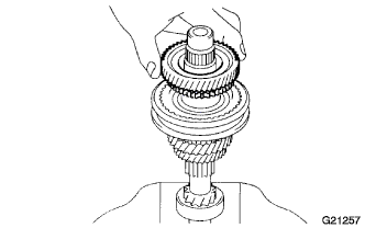
REMOVE 4TH GEAR
-
Remove the 4th gear from the input shaft.
-
-
REMOVE 4TH GEAR NEEDLE ROLLER BEARING
-
Remove the 4th gear needle roller bearing from the input shaft.
-
-
REMOVE 4TH GEAR BEARING SPACER
-
Remove the 4th gear bearing spacer from the input shaft.
-
-
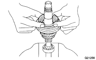
REMOVE 4TH GEAR SYNCHRONIZER RING
-
Remove the 4th gear synchronizer ring from clutch hub No. 2.
-
-
REMOVE CLUTCH HUB NO. 2 SETTING SHAFT SNAP RING
-
Using a snap ring expander, remove clutch hub No. 2 setting shaft snap ring from the input shaft.
Tech Tips
Do not damage the journal surface of the input shaft.
-
-
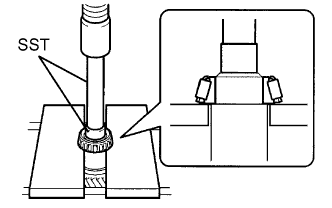
REMOVE 3RD GEAR
-
Using SST and a press, remove the hub sleeve No. 2, 3rd gear synchronizer ring and 3rd gear from the input shaft.
- SST
- 09950-00020
Note
Do not excessively tighten SST.
Tech Tips
Support the input shaft by hand to prevent it from dropping off.
-
-
REMOVE TRANSMISSION CLUTCH HUB NO. 2
-
Remove the 2 No. 2 shifting key springs from transmission clutch hub No. 2.
-
Remove transmission hub sleeve No. 2 from transmission clutch hub No. 2.
-
Remove the 3 No. 2 shifting keys from transmission clutch hub No. 2.
-
-
REMOVE 3RD GEAR NEEDLE ROLLER BEARING
-
Remove the 3rd gear needle roller bearing from the input shaft.
-
-
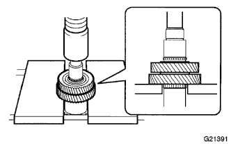
REMOVE INPUT SHAFT FRONT BEARING
-
Using a press, remove the input shaft front bearing from the input shaft.
- SST
- 09950-00020
Tech Tips
Support the input shaft by hand to prevent it from dropping off.
-
-
REMOVE OUTPUT SHAFT REAR BEARING
-
Using SST and a press, remove the output shaft rear bearing.
- SST
- 09950-60010 ( 09951-00220 )
- 09950-70010 ( 09951-07100 )
-
-
INSPECT 1ST GEAR THRUST CLEARANCE
-
Using a feeler gauge, measure the 1st gear thrust clearance.
Standard clearance 0.10 to 0.35 mm (0.0039 to 0.0138 in.) Maximum clearance 0.35 mm (0.0138)
-
-
INSPECT 2ND GEAR THRUST CLEARANCE
-
Using a feeler gauge, measure the 2nd gear thrust clearance.
Standard clearance 0.10 to 0.55 mm (0.0039 to 0.0217 in.) Maximum clearance 0.55 mm (0.0217)
-
-
INSPECT 1ST GEAR RADIAL CLEARANCE
-
Using a dial indicator, measure the 1st gear radial clearance.
Standard clearance 0.015 to 0.056 mm (0.0006 to 0.0022 in.) Maximum clearance 0.056 mm (0.0022 in.) If the clearance exceeds the maximum, replace the 1st gear, needle roller bearing or shaft.
-
-
INSPECT 2ND GEAR RADIAL CLEARANCE
-
Using a dial indicator, measure the 2nd gear radial clearance.
Standard clearance 0.015 to 0.056 mm (0.0006 to 0.0022 in.) Maximum clearance 0.056 mm (0.0022 in.) If the clearance exceeds the maximum, replace the 2nd gear, needle roller bearing or shaft.
-
-
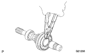
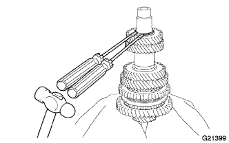
REMOVE COUNTER 5TH GEAR SHAFT SNAP RING
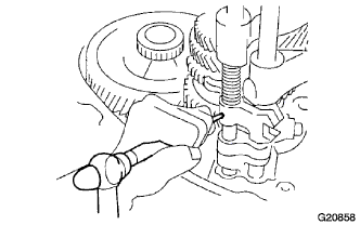
-
Using 2 screwdrivers and a hammer, remove the counter 5th gear shaft snap ring from the output shaft.
-
-
REMOVE 4TH DRIVEN GEAR
-
Using a press, remove the 5th driven gear with the 4th driven gear from the output shaft.
-
-
REMOVE OUTPUT SHAFT SPACER
-
Remove the output shaft spacer from the output shaft.
-
-
REMOVE 2ND GEAR
-
Using SST and a press, remove the 3rd driven gear with the 2nd gear from the output shaft.
- SST
- 09950-00020
-
-
REMOVE 2ND GEAR NEEDLE ROLLER BEARING
-
Remove the 2nd gear needle roller bearing from the output shaft.
-
-
REMOVE 2ND GEAR BEARING SPACER
-
Remove the 2nd gear bearing spacer from the output shaft.
-
-
REMOVE 2ND GEAR SYNCHRONIZER RING
-
Remove the 2nd gear synchronizer ring from the reverse gear.
-
-
REMOVE CLUTCH HUB NO. 1 SHAFT SNAP RING

-
Using a snap ring expander, remove the clutch hub No. 1 shaft snap ring from the output shaft.
Tech Tips
Do not damage the journal surface of the output shaft.
-
-
REMOVE 1ST GEAR
-
Using a press, remove transmission clutch hub No. 1 and the 1st gear from the output shaft.
-
-
REMOVE 1ST GEAR NEEDLE ROLLER BEARING

-
Remove the 1st gear needle roller bearing from the output shaft.
-
-
REMOVE OUTPUT SHAFT FRONT BEARING
-
Using SST and a press, remove the output shaft front bearing from the output shaft.
- SST
- 09950-00020
-
-
REMOVE TRANSMISSION CLUTCH HUB NO. 1
-
Remove the 2 No. 1 shifting key springs, 3 No. 1 shifting keys and reverse gear from transmission clutch hub No. 1.
-
-
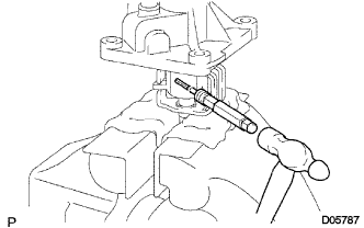
REMOVE SHIFT LEVER INNER NO. 1
-
Using a pin punch and hammer, remove the shift lever inner No. 1 slotted pin from the shift and select lever shaft.
Tech Tips
Check the orientation of shift lever inner No. 1 before removing it.
-
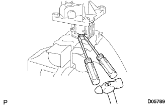
Using 2 screwdrivers and a hammer, remove the snap ring from the shift and select lever shaft.
-
Remove shift lever inner No .1 and the shift interlock plate from the shift and select lever shaft.
-
-
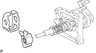
REMOVE SELECT RETURN COMPRESSION SPRING
-
Remove the select return compression spring from the shift and select lever shaft.
-
-
REMOVE SELECT SPRING SEAT NO. 2
-
Remove select spring seat No. 2 from the shift and select lever shaft.
-
-
REMOVE SELECT LEVER SHAFT
-
Remove the bolt.
-
Remove the select lever shaft from the control shaft cover.
-
-
REMOVE SELECT INNER LEVER
-
Remove the select inner lever from the control shaft cover.
-
-
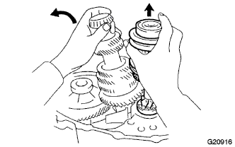
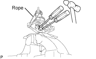
REMOVE SHIFT AND SELECT LEVER SHAFT
-
Using 2 screwdrivers and a hammer, remove the snap ring from the shift and select lever shaft.
Tech Tips
Lift the control shaft cover up with a piece of rope or equivalent to make the work easier.
-
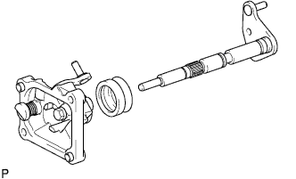
Remove the shift and select lever shaft with the shift lever boot from the control shaft cover.
-
Remove the shift lever boot from the shift and select lever shaft.
-
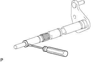
Using a small screwdriver, remove the spacer from the shift and select lever shaft.
-
-
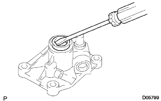
REMOVE SELECT LEVER SHAFT OIL SEAL
-
Using a screwdriver, remove the select lever shaft oil seal from the control shaft cover.
-
-
REMOVE CONTROL SHAFT COVER OIL SEAL
-
Using a screwdriver, remove the control shaft cover oil seal from the control shaft cover.
-
-
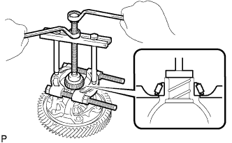
REMOVE FRONT DIFFERENTIAL CASE FRONT TAPERED ROLLER BEARING
-
Using SST, remove the front differential case front tapered roller bearing.
- SST
- 09950-00020
- 09950-00030
Tech Tips
Set the claw of SST to the bearing inner race at the indented part of the differential case.
-
-
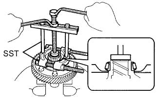
REMOVE FRONT DIFFERENTIAL CASE REAR TAPERED ROLLER BEARING
-
Using SST, remove the front differential case rear tapered roller bearing.
- SST
- 09950-00020
- 09950-00030
-
-
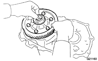
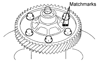
REMOVE FRONT DIFFERENTIAL RING GEAR
-
Place matchmarks on the front differential ring gear and the front differential case.
-
Remove the 6 bolts.
-
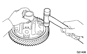
Using a hammer, remove the front differential ring gear from the front differential case.
-
-
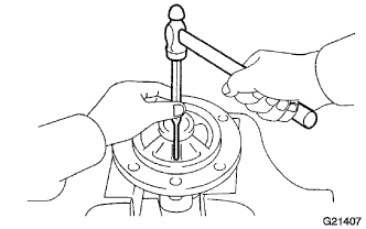
REMOVE FRONT DIFFERENTIAL CASE
-
Using a pin punch and hammer, remove the pinion shaft slotted spring pin.
-
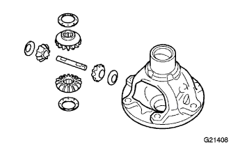
Remove the pinion shaft from the differential case.
-
Remove the 2 pinion gears, 2 side gears and the 4 thrust washers from each gear.
-