MANUAL TRANSAXLE ASSEMBLY INSTALLATION

-
INSTALL MANUAL TRANSAXLE ASSEMBLY
-
Align the input shaft with the clutch disc assembly and install the manual transaxle assembly to the engine assembly.
-
Install the 5 bolts.
- Torque:
- 64 N*m { 653 kgf*cm, 47 ft.*lbf }
Note
-
Be careful not to pinch wire harnesses, etc.
-
Do not forcefully pry on the manual transaxle assembly.
-
To avoid damage to the input shaft, do not forcefully shake the manual transaxle assembly.
-
Insert knock pins into the knock pin holes securely so that the end face of the manual transaxle assembly fits close against the engine assembly before tightening the bolts.
-
-
INSTALL ENGINE MOUNTING INSULATOR LH
-
Install the engine mounting insulator LH with engine mounting bracket to the manual transaxle assembly with the 7 bolts.
- Torque:
- 52 N*m { 530 kgf*cm, 38 ft.*lbf }
-
-
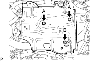
INSTALL FRONT SUSPENSION CROSSMEMBER SUB-ASSEMBLY
-
Using a transmission jack, support the front suspension crossmember sub-assembly.
-
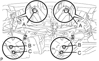
Install the front suspension crossmember sub-assembly with the 6 bolts.
- Torque:
- for bolt A
- 85 N*m { 867 kgf*cm, 63 ft.*lbf }
- for bolt B
- 128 N*m { 1305 kgf*cm, 95 ft.*lbf }
- for bolt C
- 48 N*m { 489 kgf*cm, 35 ft.*lbf }
-
Install the engine mounting control bracket with the 3 bolts.
- Torque:
- 52 N*m { 530 kgf*cm, 38 ft.*lbf }
-
Remove the engine sling device.
-
Remove the 2 bolts, No. 1 engine hanger and the No. 2 engine hanger.
-
-
INSTALL STARTER ASSEMBLY
-
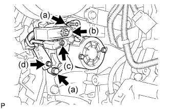
Install the starter with the 2 bolts.
- Torque:
- 37 N*m { 380 kgf*cm, 27 ft.*lbf }
-
Connect the wire harness to terminal 30 and install the nut.
- Torque:
- 9.5 N*m { 97 kgf*cm, 84 in.*lbf }
-
Connect the wire harness to terminal 50 and install the nut.
- Torque:
- 5.0 N*m { 51 kgf*cm, 44 in.*lbf }
-
Install the wire harness clamp with the bolt.
- Torque:
- 8.4 N*m { 85 kgf*cm, 74 in.*lbf }
-
-
INSTALL FRONT DRIVE SHAFT ASSEMBLIES
-
INSTALL FRONT EXHAUST PIPE ASSEMBLY
-
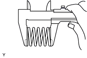
Using vernier calipers, measure the free length of the compression spring.
Minimum length 40.5 mm (1.594 in.)
-
If the length is not as specified, replace the compression spring.
-
-
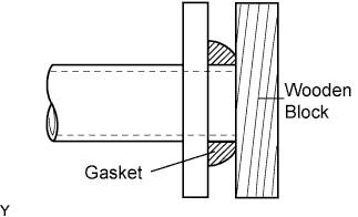
Using a plastic hammer and a wooden block, tap in a new exhaust pipe gasket until its surface is flush with the exhaust manifold.
Note
-
Be sure to install the exhaust pipe gasket in the correct direction.
-
Do not damage the outer surface of the exhaust pipe gasket.
-
Do not reuse the exhaust pipe gasket.
-
Do not push in the gasket with the exhaust pipe when connecting it.
-
-
Install the exhaust front pipe assembly and a new exhaust pipe gasket with the 2 compression springs and 2 bolts.
- Torque:
- 45 N*m { 459 kgf*cm, 33 ft.*lbf }
-
Install the exhaust pipe No.4 support.
-
Install the bolt and clamp.
- Torque:
- 32 N*m { 326 kgf*cm, 24 ft.*lbf }
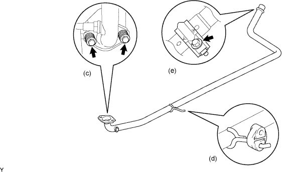
Note
-
Clamp marks and stamping should be aligned.
-
-
INSTALL FLYWHEEL HOUSING UNDER COVER
-
Install the flywheel housing under cover to the manual transaxle assembly with the 3 bolts.
- Torque:
- 40 N*m { 408 kgf*cm, 30 ft.*lbf }
-
-
INSTALL NO. 3 ENGINE WIRE
-
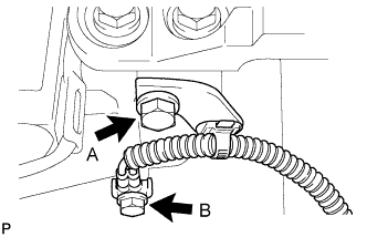
Install the No. 3 engine wire to the manual transaxle assembly with the 2 bolts.
- Torque:
- Bolt A
- 26 N*m { 260 kgf*cm, 19 ft.*lbf }
- Bolt B
- 13 N*m { 130 kgf*cm, 9 ft.*lbf }
-
-
INSTALL WIRE HARNESS CLAMP BRACKET
-
Install the wire harness clamp bracket to the manual transaxle assembly with the bolt.
- Torque:
- 13 N*m { 130 kgf*cm, 9 ft.*lbf }
-
Connect the back-up light switch connector.
-
Connect the heated oxygen sensor connector.
-
-
INSTALL CLUTCH RELEASE CABLE ASSEMBLY
-
Install the clutch release cable assembly to the manual transaxle assembly.
-
-
INSTALL TRANSMISSION CONTROL CABLE ASSEMBLY
-
Connect the transmission control shift cable to the shift lever retainer.
-
Connect the transmission control shift cable to the floor shift shift lever.
-
Connect the transmission control select cable to the shift lever retainer.
-
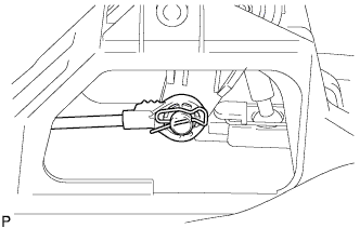
Connect the transmission control select cable to the floor shift shift lever.
Note
-
Connect the select cable point with the serrated part facing upwards.
-
Insert the clip in the orientation shown in the illustration.
-
-
-
INSTALL CLUTCH RELEASE FORK RETURN TENSION SPRING
-
Install the clutch release fork return tension spring to the release fork retracting spring hanger.
-
-
INSPECT AND ADJUST CLUTCH PEDAL SUB-ASSEMBLY
-
Turn up the floor carpet.
-
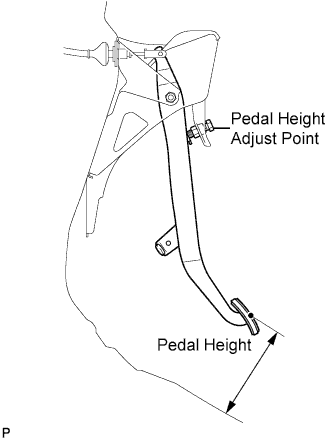
Check whether the pedal height is correct.
Pedal height from floor panel LHD 135 to 145 mm (5.31 to 5.71 in.) RHD 161 to 171 mm (6.34 to 6.74 in.) -
Adjust the pedal height.
-
Loosen the lock nut and turn the stopper bolt until the height is correct.
-
Tighten the lock nut.
- Torque:
- 25 N*m { 250 kgf*cm, 18 ft.*lbf }
-
-
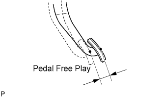
Check that the pedal free play is correct.
-
Depress the pedal until the resistance begins to be felt.
Pedal free play 13 to 23 mm (0.512 to 0.906 in.)
-
-
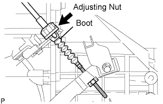
Adjust the pedal free play.
-
Turn the clutch release cable adjusting nut until the pedal free play is correct.
Note
Confirm that the clutch cable boot is installed.
-
After adjusting the pedal free play, check the pedal height.
-
-
Check the clutch release point.
-
Pull the parking brake lever and install the wheel stopper.
-
Start the engine and allow it to idle.
-
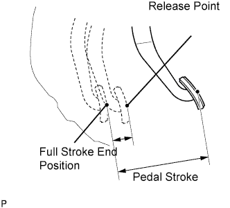
Without depressing the clutch pedal, slowly adjust the shift lever to the reverse position until the gears come into contact with the clutch pedal.
-
Gradually depress the clutch pedal and measure the stroke distance from the point that the gear noise stops (release point) up to the full stroke end position.
Standard distance 20 mm (0.787 in.) or more (from pedal stroke end position to release point) If the distance is not as specified, perform the following operations.
-
Check the pedal height.
-
Check the pedal free play.
-
Check the clutch cover and disc.
-
Check the pedal stroke.
Pedal stroke 148 mm (5.83 in.) -
-
-
-
PLACE FRONT WHEELS FACING STRAIGHT AHEAD
-
INSTALL NO. 1 STEERING COLUMN HOLE COVER SUB-ASSEMBLY
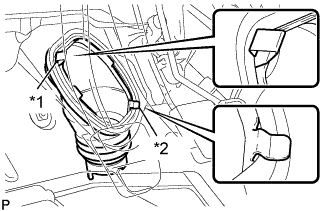
Text in Illustration *1 Clip A *2 Clip B
-
Install clip B onto the body and install the No. 1 steering column hole cover sub-assembly onto the body with clip A.
Note
Fit the lip of the No. 1 steering column hole cover sub-assembly correctly onto the dash panel.
-
-
INSTALL NO. 2 STEERING INTERMEDIATE SHAFT ASSEMBLY
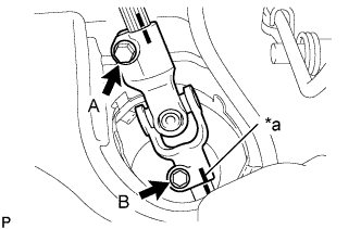
Text in Illustration *a Matchmark
-
Align the matchmarks and install the No. 2 steering intermediate shaft assembly to the steering gear assembly with bolt B.
- Torque:
- 35 N*m { 360 kgf*cm, 26 ft.*lbf }
-
Tighten bolt A.
- Torque:
- 35 N*m { 360 kgf*cm, 26 ft.*lbf }
-
Release the seat belt from the steering wheel assembly.
-
-
INSTALL STEERING COLUMN HOLE COVER PLATE
-
Engage the steering column hole cover plate.
-
-
INSTALL BATTERY CLAMP SUB-ASSEMBLY
-
Install the battery clamp sub-assembly with the 3 bolts.
- Torque:
- Bolt A
- 7.4 N*m { 75 kgf*cm, 65 in.*lbf }
- Bolt B
- 17 N*m { 175 kgf*cm, 13 ft.*lbf }
-
-
INSTALL ENGINE ROOM RELAY BLOCK
-
Engage the 3 wire harness clamps.
-
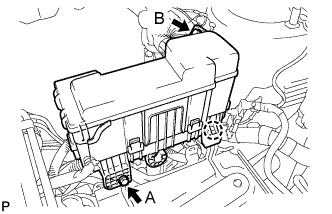
Engage the claw and install the engine room relay block.
-
Install the 2 bolts.
- Torque:
- Bolt A
- 5.4 N*m { 55 kgf*cm, 48 in.*lbf }
- Bolt B
- 8.4 N*m { 85 kgf*cm, 74 in.*lbf }
-
-
INSTALL BATTERY
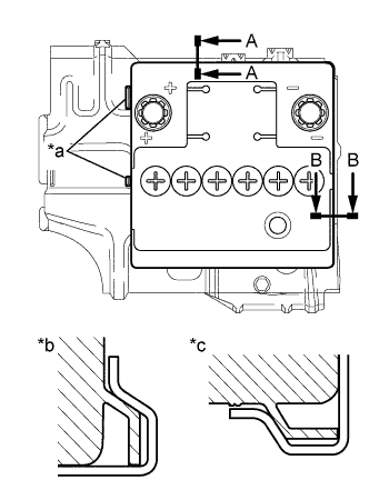
Text in Illustration *a Identification line *b A-A *c B-B
-
Install the battery onto the battery clamp sub-assembly, as shown in the illustration.
Note
-
The identification line should be seen after installing the battery.
-
The battery clamp should be in contact with the battery after the installation.
-
-
Install the battery clamp with the bolt.
- Torque:
- 15 N*m { 154 kgf*cm, 11 ft.*lbf }
-
Connect the battery positive (+) terminal with the nut.
- Torque:
- 5.4 N*m { 55 kgf*cm, 48 in.*lbf }
-
-
INSTALL COWL TOP PANEL OUTER
-
Install the cowl top panel outer with the 10 bolts.
- Torque:
- 9.2 N*m { 94 kgf*cm, 81 in.*lbf }
-
Engage the grommet and install the wire harness.
-
Engage the wire harness clamp.
-
-
INSTALL FRONT NO. 1 VENTILATOR SEAL
-
Install the No. 1 ventilator seal with the 2 clips.
-
-
INSTALL FRONT AIR SHUTTER SEAL RH
-
Install the front air shutter seal RH the 2 clips.
-
-
INSTALL FRONT WIPER MOTOR AND LINK ASSEMBLY
-
ADD MANUAL TRANSAXLE OIL
-
INSPECT MANUAL TRANSAXLE OIL
-
Stop the vehicle in a level place.
-
Remove the manual transaxle filler plug and the gasket.
-
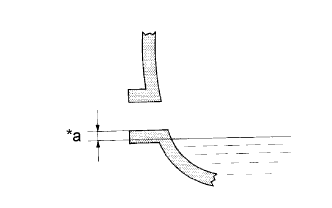
Text in Illustration *a 0 to 5 mm (0 to 0.20 in.) Check that the oil surface is within 5 mm (0.20 in.) of the bottom of the manual transaxle filler plug opening.
Note
-
Excessively large or small amounts of oil may cause trouble.
-
After replacing the oil, drive the vehicle and check the oil level again.
-
-
Check for oil leakage if the oil level is low.
-
Install the manual transaxle filler plug and a new gasket.
- Torque:
- 39 N*m { 400 kgf*cm, 29 ft.*lbf }
-
-
INSTALL FRONT WHEELS
- Torque:
- 103 N*m { 1050 kgf*cm, 76 ft.*lbf }
-
CONNECT CABLE TO NEGATIVE BATTERY TERMINAL
- Torque:
- 5.4 N*m { 55 kgf*cm, 48 in.*lbf }
-
INSPECT FRONT WHEEL ALIGNMENT
-
INSPECT FOR MANUAL TRANSAXLE OIL LEAK
-
INSPECT FOR EXHAUST GAS LEAK