INPUT SHAFT REASSEMBLY

-
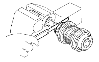
INSTALL INPUT SHAFT FRONT BEARING
-
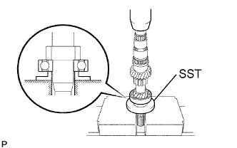
Using SST and a press, install a new input shaft front bearing to the input shaft.
- SST
- 09515-10010
-
-
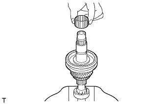
INSTALL 3RD GEAR NEEDLE ROLLER BEARING
-
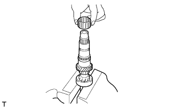
Coat the 3rd gear needle roller bearing with gear oil, and install it to the input shaft.
-
-
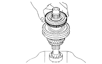
INSTALL 3RD GEAR
-
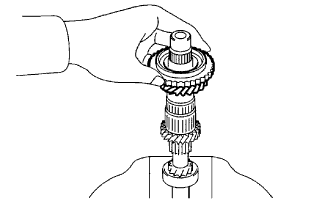
Coat the 3rd gear with gear oil, and install it to the input shaft.
-
-
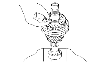
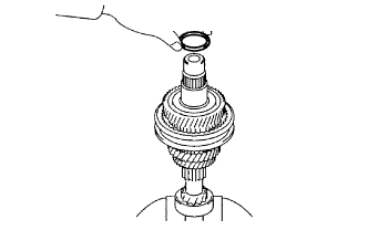
INSTALL 3RD GEAR SYNCHRONIZER RING
-
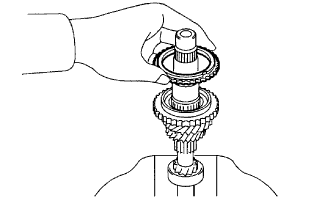
Coat the 3rd gear synchronizer ring with gear oil, and install it to the 3rd gear.
-
-
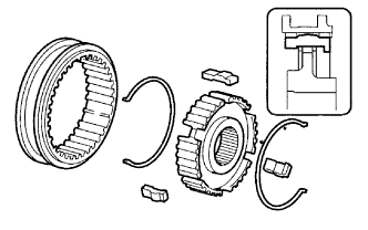
INSTALL NO. 2 TRANSMISSION CLUTCH HUB
-
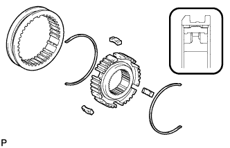
Install the No. 2 transmission hub sleeve to the No. 2 transmission clutch hub, and then install the 3 No. 2 shifting keys and the 2 No. 2 shifting key springs.
Note
Assemble the No. 2 transmission hub sleeve and the No. 2 transmission clutch hub in the correct orientations shown in the illustration.
-
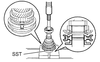
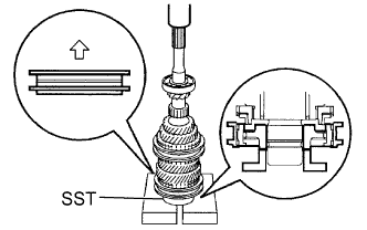
Using SST and a press, install the No. 2 transmission clutch hub set to the input shaft.
- SST
- 09506-35010
Note
-
Install the No. 2 transmission clutch hub set in the correct orientation shown in the illustration.
-
When installing the No. 2 transmission clutch hub set, align the cutout of the No. 2 transmission clutch hub with the protrusion of the 3rd gear synchronizer ring.
-
-
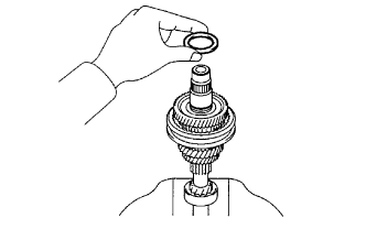
INSTALL NO. 2 CLUTCH HUB SETTING SHAFT SNAP RING
-
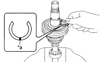
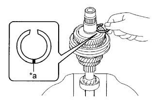
Text in Illustration *a Mark Select a new No. 2 clutch hub setting shaft snap ring that allows the minimum axial play.
Standard axial play 0.1 mm (0.00393 in.) or less. Snap Ring Thickness Part No. Mark Thickness
mm (in.)
90520-32014 A 2.28 (0.0898) 90520-32015 B 2.34 (0.0921) 90520-32016 C 2.40 (0.0945) 90520-32017 D 2.46 (0.0969) 90520-32018 E 2.52 (0.0992) 90520-32019 F 2.58 (0.1016) -
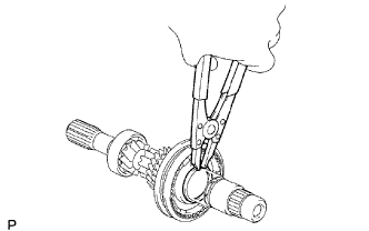
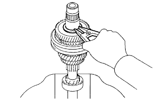
Using a snap ring expander, install the No. 2 clutch hub setting shaft snap ring to the input shaft.
Note
Do not damage the journal surface of the input shaft.
-
-
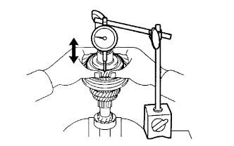
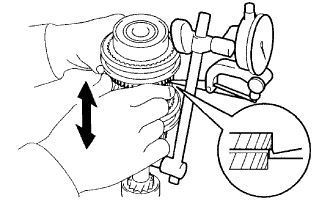
INSPECT 3RD GEAR THRUST CLEARANCE
-
Using a feeler gauge, measure the 3rd gear thrust clearance.
Standard clearance 0.10 to 0.35 mm (0.00394 to 0.0137 in.) Maximum clearance 0.35 mm (0.0137 in.) If the clearance is more than the maximum, replace the No. 2 transmission clutch hub, 3rd gear or input shaft. Replace the part or parts determined to be the most likely cause of the problem.
-
-
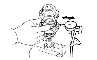
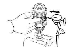
INSPECT 3RD GEAR RADIAL CLEARANCE
-
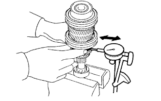
Using a dial indicator, measure the 3rd gear radial clearance.
Standard clearance 0.015 to 0.058 mm (0.000591 to 0.00228 in.) Maximum clearance 0.058 mm (0.00228 in.) If the clearance is more than the maximum, replace the 3rd gear, 3rd gear needle roller bearing or input shaft. Replace the part or parts determined to be the most likely cause of the problem.
-
-
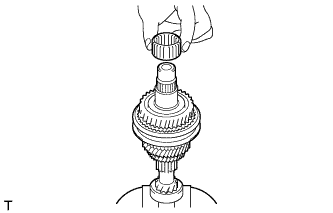
INSTALL 4TH GEAR SYNCHRONIZER RING
-
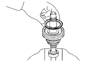
Coat the 4th gear synchronizer ring with gear oil, and install it to the No. 2 transmission clutch hub.
-
-
INSTALL 4TH GEAR BEARING SPACER
-
Coat the 4th gear bearing spacer with gear oil, and install it to the input shaft.
-
-
INSTALL 4TH GEAR NEEDLE ROLLER BEARING
-
Coat the 4th gear needle roller bearing with gear oil, and install it to the input shaft.
-
-
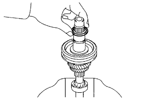
INSTALL 4TH GEAR
-
Coat the 4th gear with gear oil, and install it to the input shaft.
-
-
INSTALL 5TH GEAR THRUST WASHER BALL
-
Install the 5th gear thrust washer ball to the input shaft.
-
-
INSTALL 5TH GEAR THRUST WASHER
-
Coat the 5th gear thrust washer with gear oil, and install it to the input shaft.
-
-
INSTALL 5TH GEAR SHAFT SNAP RING
-
Text in Illustration *a Mark Using the table below, select a new 5th gear shaft snap ring that makes the thrust clearance of the 5th gear thrust washer less than 0.1 mm (0.00393 in.).
Snap Ring Thickness Part No. Mark Thickness
mm (in.)
90520-29049 1 2.28 (0.0898) 90520-29050 2 2.34 (0.0921) 90520-29052 3 2.40 (0.0945) 90520-29053 4 2.46 (0.0969) 90520-29054 5 2.52 (0.0992) 90520-29055 6 2.58 (0.1016) -
Using a snap ring expander, install the 5th gear shaft snap ring to the input shaft.
Note
Do not damage the journal surface of the input shaft.
-
-
INSPECT 4TH GEAR THRUST CLEARANCE
-
Using a dial indicator, measure the 4th gear thrust clearance.
Standard clearance 0.10 to 0.55 mm (0.00394 to 0.0216 in.) Maximum clearance 0.55 mm (0.0216 in.) If the clearance is more than the maximum, replace the No. 2 transmission clutch hub, 4th gear or 5th gear thrust washer. Replace the part or parts determined to be the most likely cause of the problem.
-
-
INSPECT 4TH GEAR RADIAL CLEARANCE
-
Using a dial indicator, measure the 4th gear radial clearance.
Standard clearance 0.015 to 0.058 mm (0.000591 to 0.00228 in.) Maximum clearance 0.058 mm (0.00228 in.) If the clearance is more than the maximum, replace the 4th gear, 4th gear needle roller bearing or input shaft. Replace the part or parts determined to be the most likely cause of the problem.
-
-
INSTALL 5TH GEAR BEARING SPACER
-
Coat the 5th gear bearing spacer with gear oil, and install it to the input shaft.
-
-
INSTALL 5TH GEAR NEEDLE ROLLER BEARING
-
Coat the 5th gear needle roller bearing with gear oil, and install it to the input shaft.
-
-
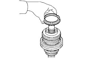
INSTALL 5TH GEAR
-
Coat the 5th gear with gear oil, and install it to the input shaft.
-
-
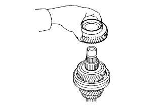
INSTALL 5TH GEAR SYNCHRONIZER RING
-
Coat the 5th gear synchronizer ring with gear oil, and install it to the 5th gear.
-
-
INSTALL NO. 3 TRANSMISSION CLUTCH HUB
-
Install the No. 3 transmission hub sleeve to the No. 3 transmission clutch hub, and then install the 3 No. 3 shifting keys and the 2 No. 3 shifting key springs.
Note
Assemble the No. 3 transmission hub sleeve, 3 No. 3 shifting keys and the No. 3 transmission clutch hub in the correct orientations shown in the illustration.
-
Place the 5th gear synchronizer ring on the 5th gear, and align the synchronizer ring slots with the No. 3 shifting keys.
-
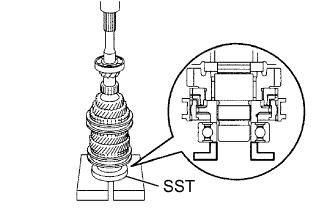
Using SST and a press, install the No. 3 transmission clutch hub set to the input shaft.
- SST
- 09515-10010
Note
Install the No. 3 transmission clutch hub set in the correct orientation as shown in the illustration.
-
-
INSTALL INPUT SHAFT REAR RADIAL BALL BEARING
-
Using SST and a press, install a new input shaft rear radial ball bearing to the input shaft.
- SST
- 09515-10010
-
-
INSPECT 5TH GEAR THRUST CLEARANCE
-
Using a dial indicator, measure the 5th gear thrust clearance.
Standard clearance 0.10 to 0.50 mm (0.00394 to 0.0196 in.) Maximum clearance 0.50 mm (0.0196 in.) If the clearance is more than the maximum, replace the No. 3 transmission clutch hub, 5th gear or 5th gear thrust washer. Replace the part or parts determined to be the most likely cause of the problem.
-
-
INSPECT 5TH GEAR RADIAL CLEARANCE
-
Using a dial indicator, measure the 5th gear radial clearance.
Standard clearance 0.015 to 0.058 mm (0.000591 to 0.00228 in.) Maximum clearance 0.058 mm (0.00228 in.) If the clearance is more than the maximum, replace the 5th gear, 5th gear needle roller bearing or input shaft. Replace the part or parts determined to be the most likely cause of the problem.
-