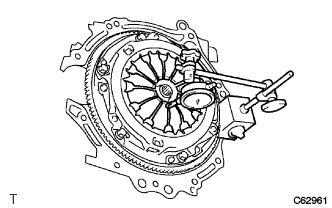
CLUTCH UNIT (for C553) INSTALLATION

-
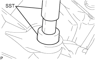
INSTALL CLUTCH DISC ASSEMBLY
-
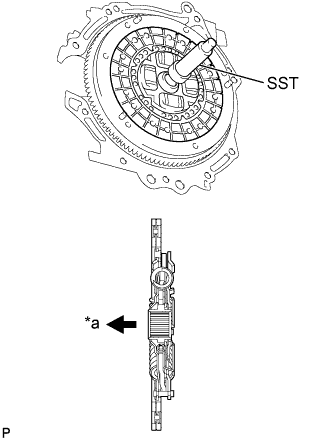
Text in Illustration *a Flywheel Side Insert SST into the clutch disc, and then insert them into the flywheel.
- SST
- 09301-00131
Note
Do not insert the clutch disc in the wrong direction.
-
-
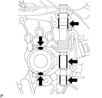
INSTALL CLUTCH COVER ASSEMBLY
-
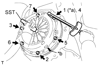
Text in Illustration *a Temporarily *b Matchmark Align the matchmark on the clutch cover with the one on the flywheel.
-
Tighten the 6 bolts uniformly in the order shown in the illustration, starting with the bolt located near the knock pin on the top.
- Torque:
- 19 N*m { 195 kgf*cm, 14 ft.*lbf }
Tech Tips
After checking that the disc is in the center, gently move SST up and down, right and left to tighten the bolts.
- SST
- 09301-00131
-
-
INSPECT AND ADJUST CLUTCH COVER ASSEMBLY
-
Using a dial indicator with a roller instrument, check the diaphragm spring tip alignment.
Maximum non-alignment 0.5 mm (0.0197 in.) -
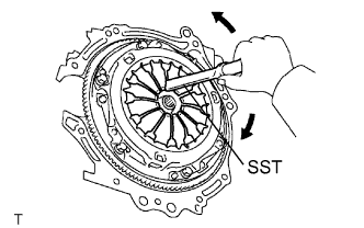
If the alignment is not as specified, using SST, adjust the diaphragm spring tip alignment.
- SST
- 09333-00013
-
-
INSTALL NO. 1 CLUTCH HOUSING COVER
-
Install the No. 1 clutch housing cover onto the transaxle case.
-
-
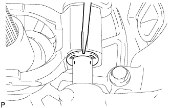
INSTALL CLUTCH RELEASE FORK LEVER SHAFT OIL SEAL
-
Using SST and a hammer, tap in a new select lever shaft oil seal until its surface is flush with the manual transaxle case.
- SST
- 09950-60010 ( 09951-00290 )
- 09950-70010 ( 09951-07150 )
-
-
INSTALL CLUTCH RELEASE FORK LEVER
-
Apply release hub grease to the contact surface between the release bearing and the release fork, the rotating and sliding parts of the release lever and the spline coupling part.
Text in Illustration 
Release hub grease Grease Toyota Genuine Release Hub Grease or equivalent Note
Apply grease uniformly to the rotating and sliding parts of the release lever and spline coupling part. Remove any grease extending beyond the release lever joining part.
-
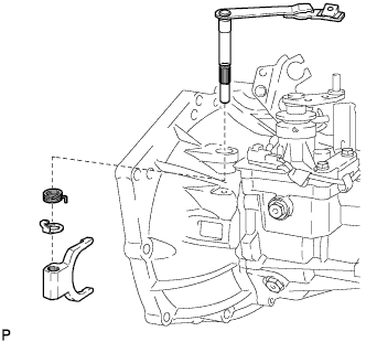
Install the release fork lever onto the transaxle case together with the torsion spring, spring stopper and the release fork.
-
Using a screwdriver and hammer, install a new E-ring.
-
Secure the torsion spring to the release fork.
Note
Hold the spring and spring stopper up to the upper end of the release fork lever first, and then secure the spring.
-
-
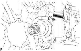
INSTALL CLUTCH RELEASE BEARING ASSEMBLY
-
Apply clutch spline grease to the input shaft spline.
Grease Toyota Genuine Clutch Spline Grease or equivalent -
Install the release bearing onto the transaxle case.
-
-
INSTALL RELEASE FORK RETRACTING SPRING HANGER
-
Install the release fork retracting spring hanger onto the release fork lever with the bolt.
- Torque:
- 33 N*m { 336 kgf*cm, 24 ft.*lbf }
-
-
INSTALL MANUAL TRANSAXLE ASSEMBLY