CLUTCH UNIT (for C552) INSTALLATION

-
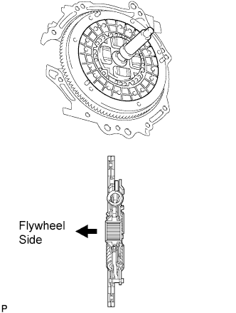
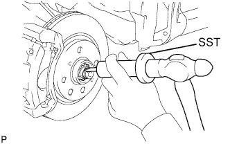
INSTALL CLUTCH DISC ASSEMBLY
-
Insert SST into the clutch disc, and then insert them into the flywheel.
- SST
- 09301-00131
Note
Do not insert the clutch disc in the wrong direction.
-
-
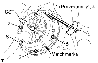
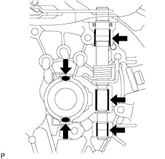
INSTALL CLUTCH COVER ASSEMBLY
-
Align the matchmark on the clutch cover with the one on the flywheel.
-
Tighten the 6 bolts uniformly in the order shown in the illustration, starting with the bolt located near the knock pin on the top.
- Torque:
- 19 N*m { 195 kgf*cm, 14 ft.*lbf }
Tech Tips
After checking that the disc is in the center, gently move SST up and down, right and left to tighten the bolts.
- SST
- 09301-00131
-
-
INSPECT AND ADJUST CLUTCH COVER ASSEMBLY
-
Using a dial indicator with a roller instrument, check the diaphragm spring tip alignment.
Maximum non-alignment 0.5 mm (0.0197 in.) -
If the alignment is not as specified, using SST, adjust the diaphragm spring tip alignment.
-
-
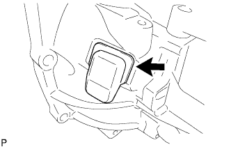
INSTALL CLUTCH HOUSING COVER NO.1
-
Install clutch housing cover No. 1 onto the manual transaxle case.
-
-
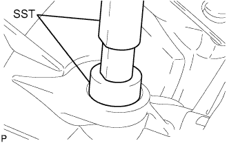
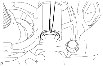
INSTALL CLUTCH RELEASE FORK LEVER SHAFT OIL SEAL
-
Using SST and a hammer, tap in a new select lever shaft oil seal until its surface is flush with the manual transaxle case.
-
-
INSTALL CLUTCH RELEASE FORK LEVER
-
Apply clutch release grease to the contact surface between the release bearing and the release fork, the rotating and sliding parts of the release lever and the spline coupling part.
Note
Apply grease uniformly to the rotating and sliding parts of the release lever and spline coupling part.
Remove any grease extending beyond the release lever joining part.
-
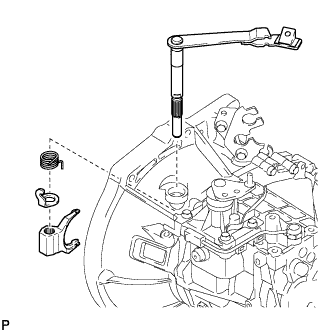
Install the release fork lever onto the transaxle case together with the torsion spring, spring stopper and the release fork.
-
Using a screwdriver and hammer, install a new E-ring.
-
Secure the torsion spring to the release fork.
Note
Hold the spring and spring stopper up to the upper end of the release fork lever first, and then secure the spring.
-
-
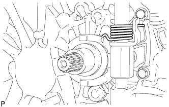
INSTALL CLUTCH RELEASE BEARING ASSEMBLY
-
Install the release bearing onto the transaxle case.
-
-
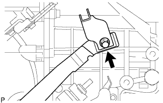
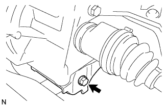
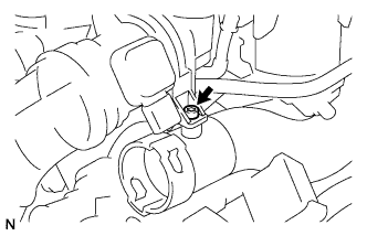
INSTALL RELEASE FORK RETRACTING SPRING HANGER
-
Install the release fork retracting spring hanger onto the release fork lever with the bolt.
- Torque:
- 33 N*m { 336 kgf*cm, 24 ft.*lbf }
-
-
INSTALL MANUAL TRANSAXLE ASSEMBLY
-
Align the input shaft with the clutch disc and install the manual transaxle onto the engine.
-
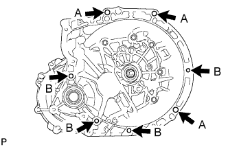
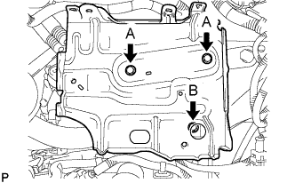
Install the 7 bolts.
- Torque:
- 40 N*m { 408 kgf*cm, 30 ft.*lbf }
Tech Tips
-
Install 3 A bolts from the transaxle side.
-
Install 4 B bolts from the engine side.
-
-
INSTALL STARTER ASSEMBLY
-
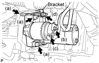
Using a hexagon wrench (6 mm), install the starter with the 3 bolts.
- Torque:
- 20 N*m { 204 kgf*cm, 15 ft.*lbf }
-
Connect the wire harness to terminal 30 and install the nut.
- Torque:
- 10 N*m { 102 kgf*cm, 7 ft.*lbf }
-
Connect the wire harness to terminal 50 and install the nut.
- Torque:
- 5.0 N*m { 51 kgf*cm, 44 in.*lbf }
-
Install the wire harness clamp bracket with the bolt.
- Torque:
- 20 N*m { 204 kgf*cm, 15 ft.*lbf }
-
-
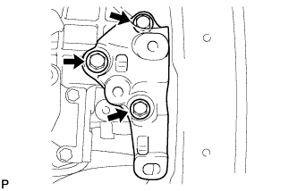
INSTALL ENGINE MOUNTING BRACKET
-
Install the engine mounting bracket onto the manual transaxle with the 3 bolts.
- Torque:
- 52 N*m { 530 kgf*cm, 38 ft.*lbf }
-
-
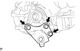
INSTALL ENGINE MOVING CONTROL ROD BRACKET
-
Install the engine moving control rod bracket onto the manual transaxle with the 3 bolts.
- Torque:
- 52 N*m { 530 kgf*cm, 38 ft.*lbf }
-
-
INSTALL FRONT SUSPENSION CROSSMEMBER SUB-ASSEMBLY
-
Install the engine with transaxle assembly to the crossmember sub-assembly and the engine mounting member with the bolt.
- Torque:
- 120 N*m { 1,224 kgf*cm, 89 ft.*lbf }
-
Set the engine lifter.
-
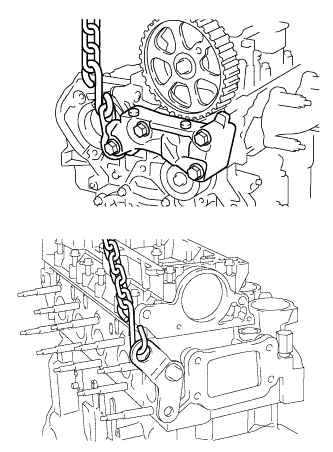
Remove the chain block from the engine assembly with transaxle.
-
-
INSTALL EXHAUST MANIFOLD CONVERTER SUB-ASSEMBLY
-
Using "Torx" socket (E7), install the stud bolt.
- Torque:
- 8 N*m { 82 kgf*cm, 71 in.*lbf }
-
Provisionally install the exhaust manifold converter clamp, converter separator insulator No.1, catalytic converter support bracket, exhaust manifold converter sub-assembly with the 3 nuts.
-
Tighten the 2 nuts on the cylinder block.
- Torque:
- 25 N*m { 255 kgf*cm, 18 ft.*lbf }
-
Tighten the nut on the exhaust manifold converter clamp.
- Torque:
- 25 N*m { 255 kgf*cm, 18 ft.*lbf }
-
-
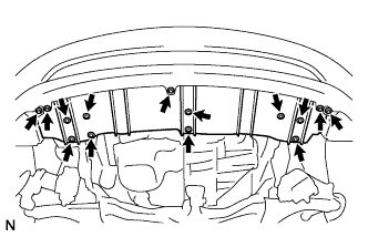
INSTALL TURBO INSULATOR NO.1
-
Install the turbo insulator No.1 with the 7 bolts.
- Torque:
- 4.0 N*m { 41 kgf*cm, 35 in.*lbf }
-
-
INSTALL TIMING BELT UPPER COVER
-
Install the timing belt upper cover with the 5 bolts.
- Torque:
- 5.0 N*m { 51 kgf*cm, 44 in.*lbf }
-
-
INSTALL ENGINE ASSEMBLY WITH TRANSAXLE
-
Install the engine with transaxle.
-
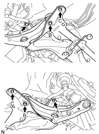
Tighten the 6 bolts.
- Torque:
- For A
- 85 N*m { 867 kgf*cm, 63 ft.*lbf }
- For B
- 128 N*m { 1,306 kgf*cm, 95 ft.*lbf }
- For C
- 48 N*m { 490 kgf*cm, 35 ft.*lbf }
-
Tighten the 3 bolts.
- Torque:
- 52 N*m { 530 kgf*cm, 38 ft.*lbf }
-
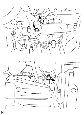
Tighten the nut.
- Torque:
- 52 N*m { 530 kgf*cm, 38 ft.*lbf }
-
Tighten the 2 bolts.
- Torque:
- 52 N*m { 530 kgf*cm, 38 ft.*lbf }
-
-
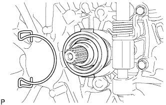
INSTALL FRONT DRIVE SHAFT ASSEMBLY LH
-
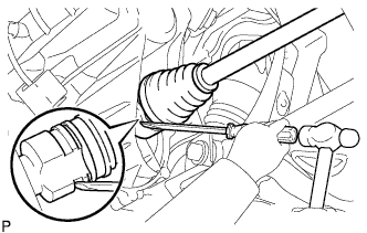
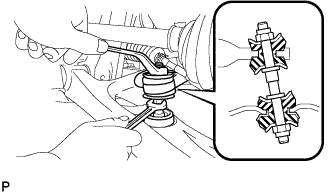
Coat the spline of the inboard joint shaft assembly with transaxle oil.
-
Align the shaft splines and install the drive shaft assembly with a screwdriver and hammer.
Note
-
Face the snap ring cut area downward.
-
Do not damage the oil seal.
-
Do not damage the front drive shaft assembly boot.
Tech Tips
Whether the front drive shaft assembly is securely driven in or not can be confirmed from the brass bar reaction force or sound.
-
-
-
INSTALL FRONT DRIVE SHAFT ASSEMBLY RH
Tech Tips
The installation procedure for the RH side is the same as that for the LH side.
-
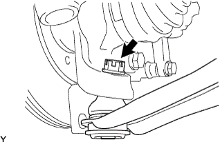
INSTALL FRONT AXLE ASSEMBLY LH
-
Push the front axle assembly out of the vehicle to align the spline of the front drive shaft assembly with the front axle assembly and insert the front axle assembly.
Note
-
Do not push the front axle assembly further out of the vehicle than is necessary.
-
Do not damage the oil seal.
-
Do not damage the front drive shaft assembly boot.
-
Do not damage the speed sensor rotor.
-
Check for any foreign matter on the speed sensor rotor and insertion part.
-
-
-
INSTALL FRONT AXLE ASSEMBLY RH
Tech Tips
The installation procedure for the RH side is the same as that for the LH side.
-
INSTALL FRONT SUSPENSION ARM SUB-ASSEMBLY LOWER NO. 1 LH
-
Push the front suspension lower arm No. 1 downward, install the front lower ball joint and tighten the castle nut and a new clip.
- Torque:
- 98 N*m { 1,000 kgf*cm, 72 ft.*lbf }
Note
Retighten the castle nut and clip within a turning angle of 60° after aligning the hole of the clip with the castle nut.
-
-
INSTALL FRONT SUSPENSION ARM SUB-ASSEMBLY LOWER NO. 1 RH
Tech Tips
The installation procedure for the RH side is the same as that for the LH side.
-
INSTALL STABILIZER BAR FRONT
-
Install the stabilizer bar front with the 2 cushion retainers, 2 cushions and a nut, as shown in the illustration.
Note
Be sure to install the cushion and retainer in the correct direction.
-
Tighten the nut with a spanner (10 mm).
- Torque:
- 18 N*m { 184 kgf*cm, 13 ft.*lbf }
-
-
INSTALL TIE ROD END SUB-ASSEMBLY LH
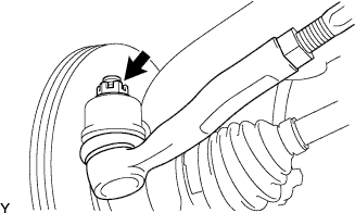
-
Connect the tie rod end to the steering knuckle and install it with the castle nut and a new cotter pin.
- Torque:
- 33 N*m { 336 kgf*cm, 24 ft.*lbf }
Note
Retighten the castle nut and cotter pin within a turning angle of 60° after aligning the hole of the cotter pin with the castle nut.
-
-
INSTALL TIE ROD END SUB-ASSEMBLY RH
Tech Tips
The installation procedure for the RH side is the same as that for the LH side.
-
INSTALL FRONT AXLE SHAFT LH NUT
-
Install a new front axle hub nut.
- Torque:
- 216 N*m { 2,202 kgf*cm, 160 ft.*lbf }
-
Using a hammer and chisel, stake the front axle hub nut.
-
-
INSTALL FRONT AXLE SHAFT RH NUT
Tech Tips
The installation procedure for the RH side is the same as that for the LH side.
-
INSTALL FRONT WHEELS
- Torque:
- 103 N*m { 1050 kgf*cm, 76 ft.*lbf }
-
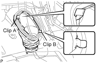
INSTALL STEERING COLUMN HOLE COVER SUB-ASSEMBLY NO.1
-
Install clip B onto the vehicle body and install the steering column hole cover onto the vehicle body with clip A.
Note
Fit the lip of the steering column hole cover correctly onto the dash panel.
-
-
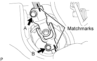
INSTALL STEERING INTERMEDIATE SHAFT ASSEMBLY NO. 2
-
Align the matchmarks and install steering intermediate shaft assembly No. 2 onto the steering gear sub-assembly with bolt B.
- Torque:
- 35 N*m { 360 kgf*cm, 26 ft.*lbf }
-
Tighten bolt A.
- Torque:
- 35 N*m { 360 kgf*cm, 26 ft.*lbf }
-
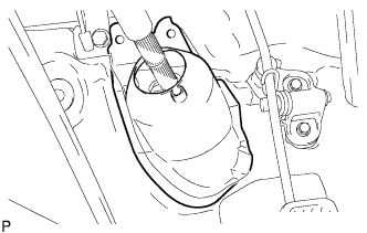
Release the seat belt from the steering wheel.
-
-
INSTALL STEERING COLUMN HOLE COVER PLATE
-
Engage the steering hole plate.
-
-
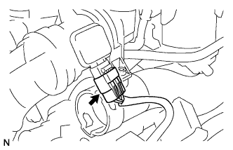
INSTALL CLUTCH RELEASE CABLE ASSEMBLY
-
Connect the clutch release cable to the manual transaxle.
-
-
INSPECT AND ADJUST CLUTCH PEDAL SUB-ASSEMBLY
-
Turn up the floor carpet.
-
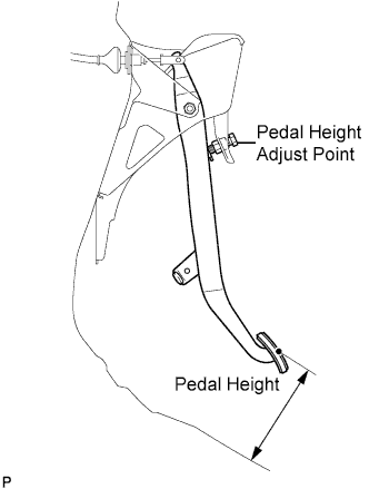
Check whether the pedal height is correct.
Pedal height from floor panel LHD 135 to 145 mm (5.31 to 5.71 in.) RHD 161 to 171 mm (6.34 to 6.74 in.) -
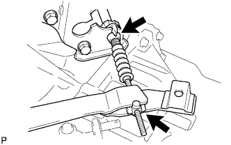
Adjust the pedal height.
-
Loosen the lock nut and turn the stopper bolt until the height is correct.
-
Tighten the lock nut.
- Torque:
- 25 N*m { 250 kgf*cm, 18 ft.*lbf }
-
-
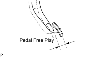
Check that the pedal free play is correct.
-
Depress the pedal until the resistance begins to be felt.
Pedal free play 13 to 23 mm (0.512 to 0.906 in.)
-
-
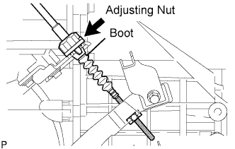
Adjust the pedal free play.
-
Turn the clutch release cable adjusting nut until the pedal free play is correct.
Note
Confirm that the clutch cable boot is installed.
-
After adjusting the pedal free play, check the pedal height.
-
-
Check the clutch release point.
-
Pull the parking brake lever and install the wheel stopper.
-
Start the engine and allow it to idle.
-
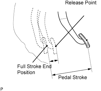
Without depressing the clutch pedal, slowly adjust the shift lever to the reverse position until the gears come into contact with the clutch pedal.
-
Gradually depress the clutch pedal and measure the stroke distance from the point that the gear noise stops (release point) up to the full stroke end position.
Standard distance 20 mm (0.787 in.) or more (from pedal stroke end position to release point) If the distance is not as specified, perform the following operations.
-
Check the pedal height.
-
Check the pedal free play.
-
Check the clutch cover and disc.
-
Check the pedal stroke.
Pedal stroke 148 mm (5.83 in.) -
-
-
-
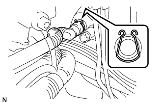
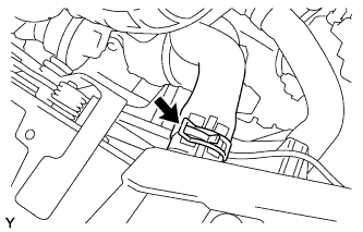
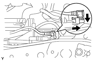
INSTALL TRANSMISSION CONTROL CABLE ASSEMBLY
-
Connect the transmission control shift cable to the shift lever retainer.
-
Connect the transmission control shift cable to the floor shift shift lever.
-
Connect the transmission control select cable to the shift lever retainer.
-
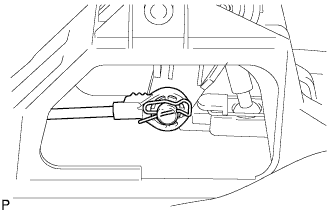
Connect the transmission control select cable to the floor shift shift lever.
Note
-
Connect the select cable with the serrated part on the tip facing upward.
-
Insert the clip in the correct orientation, as shown in the illustration.
-
-
-
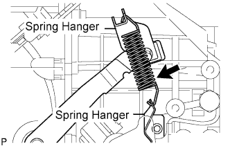
INSTALL CLUTCH RELEASE FORK RETURN TENSION SPRING
-
Install the clutch release fork return tension spring onto the release fork retracting spring hanger.
-
-
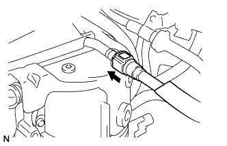
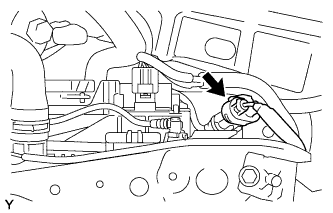
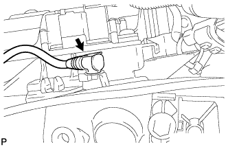
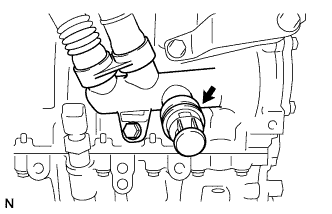
CONNECT FUEL MAIN TUBE
-
Align the connector with the pipe, then push in the connector to the pipe until it makes a "click" sound to connect the fuel tube sub-assembly.
-
-
INSTALL FUEL FILTER PROTECTOR NO.1
-
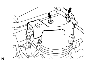
Using a "torx" socket wrench, install the fuel filter protector with the screws.
- Torque:
- 20 N*m { 204 kgf*cm, 15 ft.*lbf }
-
-
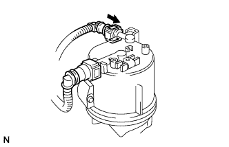
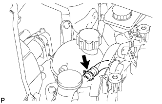
CONNECT FUEL RETURN TUBE
-
Align the connector with the pipe, then push in the connector to the pipe until it makes a "click" sound to connect the fuel return tube sub-assembly to the fuel filter.
-
-
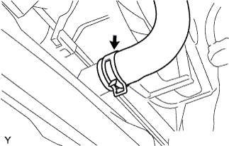
CONNECT HEATER WATER OUTLET HOSE A
-
Insert the heater water outlet hose A.
-
Install the clip.
-
-
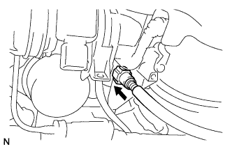
CONNECT HEATER WATER HOSE INLET A
-
Using pliers, slide the clip to connect the heater water inlet hose A.
-
-
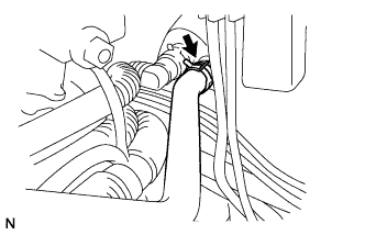
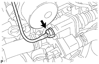
CONNECT VACUUM HOSE ASSEMBLY
-
Align the connector with the pipe, then push in the connector to the pipe until it makes a "click" sound to connect the vacuum hose assembly to the vacuum pump.
-
-
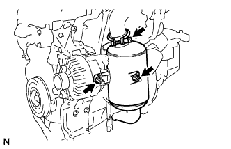
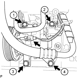
INSTALL COMPRESSOR AND MAGNETIC CLUTCH (w/ Air Conditioning System)
-
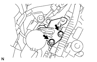
Provisionally tighten the compressor and magnetic clutch with the 4 bolts.
-
Tighten the compressor and magnetic clutch with the 4 bolts.
- Torque:
- 25 N*m { 255 kgf*cm, 18 ft.*lbf }
Note
Tighten the bolts in the sequence order shown in the illustration to install the compressor and magnetic clutch.
-
Connect the connector.
-
-
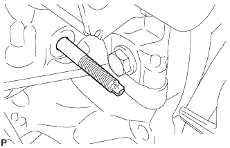
INSTALL FAN & GENERATOR V BELT
-
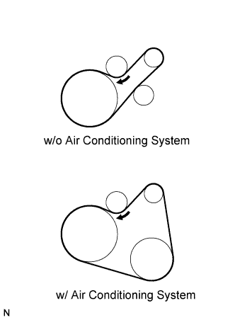
Install the belt.
-
While turning the belt tensioner clockwise, remove the bar.
-
-
INSTALL EXHAUST PIPE ASSEMBLY FRONT
-
Install the exhaust front pipe assembly with a new clamp.
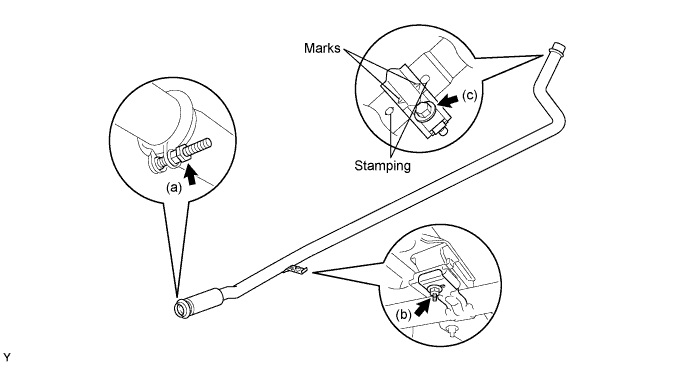
- Torque:
- 25 N*m { 255 kgf*cm, 18 ft.*lbf }
-
Install the exhaust front pipe stay nut and exhaust pipe support No.4.
- Torque:
- 7.7 N*m { 79 kgf*cm, 68 ft.*lbf }
-
Install a new clamp and bolt.
- Torque:
- 32 N*m { 326 kgf*cm, 24 ft.*lbf }
Note
The clamp marks and stampings should be aligned.
-
-
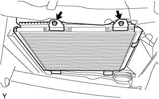
INSTALL RADIATOR ASSEMBLY
-
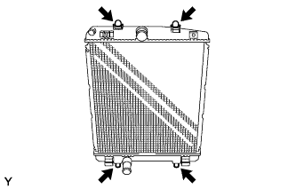
Install the 2 radiator support cushions and 2 grommets to the radiator assembly.
-
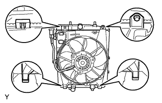
Install the fan assembly to the radiator assembly, with the claws and tighten the bolt.
- Torque:
- 7.5 N*m { 76 kgf*cm, 66 in.*lbf }
-
-
INSTALL FRONT CROSS MEMBER SUB-ASSEMBLY
-
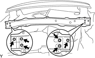
Install the front cross member sub-assembly with the 6 bolts.
- Torque:
- 5.5 N*m { 56 kgf*cm, 49 in.*lbf }
-
-
CONNECT CONDENSER ASSEMBLY (w/ Air Conditioning System)
-
Install the radiator assembly with the 2 bolts.
- Torque:
- 9.8 N*m { 100 kgf*cm, 87 in.*lbf }
-
-
INSTALL RADIATOR HOSE OUTLET
-
Connect the radiator hose No.2 with a new clamp.
-
-
INSTALL RADIATOR HOSE INLET
-
Connect the radiator hose with a new clamp.
-
-
CONNECT COOLING FAN RESISTOR CONNECTOR (w/ Air Conditioning System)
-
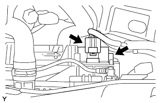
Connect the 2 resistor connectors.
-
-
CONNECT COOLING FAN MOTOR CONNECTOR
-
Connect the cooling fan motor connector.
-
-
INSTALL RADIATOR SIDE AIR SEAL NO.1
-
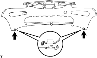
INSTALL FRONT BUMPER COVER
-
Install the 2 clips.
-
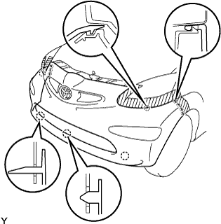
Engage the 13 claws and install the front bumper cover.
-
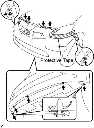
Tighten the 3 bolts and 5 screws.
-
Install the 3 clips.
-
Remove the protective tape.
-
-
INSTALL WATER BY-PASS HOSE NO.2
-
Insert the water by-pass hose No.2 to the thermostat housing.
-
Install the clip.
-
-
INSTALL WATER BY-PASS HOSE
-
Insert the water by-pass hose to the radiator assembly.
-
Install the clip.
-
-
INSTALL RADIATOR RESERVE TANK ASSEMBLY
-
Install the radiator reserve tank with the bolt.
- Torque:
- 7.5 N*m { 77 kgf*cm, 66 in.*lbf }
-
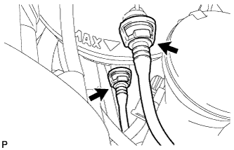
Insert the 2 water by-pass hoses.
-
Install the 2 clips.
-
Insert the fuel by-pass hose No.5.
-
Install the clip.
-
-
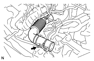
INSTALL AIR CLEANER INLET NO.2
-
Using a "torx" socket wrench, install the inlet air cleaner No.2 with the screw.
- Torque:
- 2.0 N*m { 20 kgf*cm, 18 in.*lbf }
-
Connect the mass air flow meter connector.
-
-
INSTALL AIR CLEANER INLET NO.1
-
Install inlet air cleaner.
-
-
INSTALL BATTERY CLAMP SUB-ASSEMBLY
-
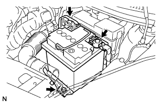
Install the battery clamp with the 3 bolts.
- Torque:
- Bolt A
- 7.4 N*m { 75 kgf*cm, 65 in.*lbf }
- Bolt B
- 17 N*m { 175 kgf*cm, 13 ft.*lbf }
-
Engage the 2 wire harness clamps.
-
-
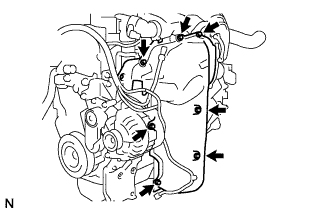
CONNECT ENGINE WIRE
-
Connect the battery terminal B with the nut.
- Torque:
- 14 N*m { 143 kgf*cm, 10 ft.*lbf }
-

Connect the 2 ground terminals with the 2 bolts.
-
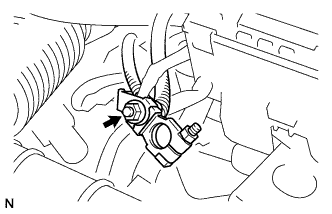
Connect the glow relay connector.
-
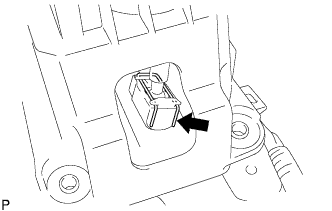
Push the retainer as shown in the illustration.
-
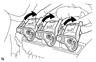
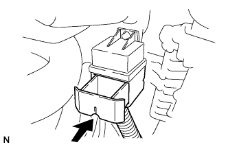
Connect the ECM connectors to the ECM.
-
Turn the retainers as shown in the illustration.
-
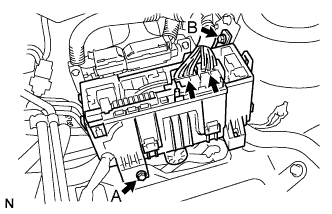
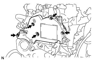
Install the engine relay block with the bolt.
- Torque:
- For A
- 5.4 N*m { 55 kgf*cm, 48 in.*lbf }
- For B
- 8.4 N*m { 86 kgf*cm, 74 in.*lbf }
-
Connect the engine wire harness connectors to the engine room relay block.
-
-
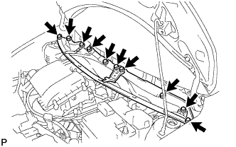
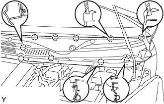
INSTALL COWL TOP PANEL OUTER
-
Install the cowl top panel with the 10 bolts.
- Torque:
- 9.2 N*m { 94 kgf*cm, 81 in.*lbf }
-
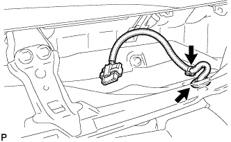
Install the grommet of the wire harness.
-
Install the clamp of the wire harness.
-
-
INSTALL FRONT WIPER MOTOR AND LINK ASSEMBLY
-
Connect the connector.
-
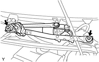
Install the front wiper motor and link assembly with the 2 bolts.
- Torque:
- 13 N*m { 127 kgf*cm, 9 ft.*lbf }
-
-
INSTALL COWL TOP VENTILATOR LOUVER RH
-
Connect the washer hose.
-

Engage the 8 claws and install the cowl top ventilator louver RH.
-
Install the clip.
-
-
INSTALL COWL TOP VENTILATOR LOUVER LH
-
Connect the washer hose.
-
Engage the 9 claws and install the cowl top ventilator louver LH.
-
Install the clip.
-
-
INSTALL HOOD TO COWL TOP SEAL

-
Engage the 8 clips and install the hood to cowl top seal.
-
-
INSTALL FRONT WIPER ARM LH
-
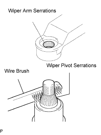
Scrape any metal powder off the serrated part of the wiper arm with a round file or equivalent (when reinstalling).
-
Clean the wiper pivot serrations with a wire brush.
-
Operate the wiper, then stop the windshield wiper motor assembly in the automatic stop position.
-
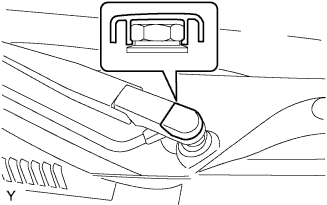
Provisionally install the front wiper main arm with the nut.
-
Install the front wiper secondary arm onto the front wiper motor and link assembly.
-
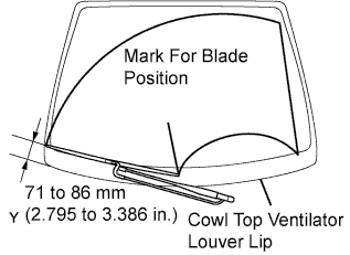
Align the blade tip with the mark on the windshield glass, as shown in the illustration.
-
Tighten the nut of the front wiper main arm.
- Torque:
- 21 N*m { 209 kgf*cm, 15 ft.*lbf }
-
-
INSTALL FRONT WIPER ARM HEAD CAP
-
Engage the claw and install the front wiper arm head cap.
-
-
INSTALL BATTERY
-
Install the battery and clamp with the bolt.
- Torque:
- 15 N*m { 154 kgf*cm, 11 ft.*lbf }
-
Connect the positive battery cable.
- Torque:
- 5.4 N*m { 55 kgf*cm, 48 in.*lbf }
-
-
INSTALL ENGINE COVER NO.1
-
CONNECT CABLE TO NEGATIVE BATTERY TERMINAL
- Torque:
- 5.4 N*m { 55 kgf*cm, 48 in.*lbf }
-
ADD MANUAL TRANSAXLE OIL
-
INSPECT MANUAL TRANSAXLE OIL
-
Stop the vehicle in a level place.
-
Remove the transmission filler plug and the gasket.
-
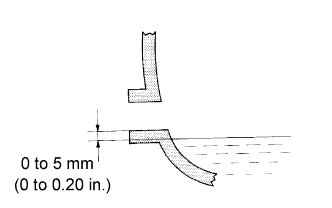
Check that the oil surface is within 5 mm (0.20 in.) of the lowest point of the transmission filler plug opening.
Note
-
Excessively large or small amounts of oil may cause problems.
-
After replacing the oil, drive the vehicle and check the oil level again.
-
-
When the oil level is low, check for oil leakage.
-
Install the transmission filler plug and a new gasket.
- Torque:
- 39 N*m { 400 kgf*cm, 29 ft.*lbf }
-
-
ADD ENGINE COOLANT
-
Install the drain plug with an O-ring and a new clip.
-
Connect the radiator hose No.2.
-
Pour engine coolant into the reserve tank assembly.
Capacity 4.0 to 4.4 L Note
Do not substitute water for engine coolant.
Tech Tips
-
Use of improper engine coolant may damage the engine coolant system.
-
Use only Premium Long Life Coolant for 1WZ and 2WZ-TV. Pre-mixed. Green. or similar high quality ethylene glycol based non-silicate, non-amine, non-nitrite, and non-borate engine coolant with long-life hybrid organic acid technology (coolant with long-life hybrid organic acid technology consists of a combination of low phosphates and organic acids).
-
-
Check the engine coolant level inside the radiator assembly by pressing the inlet and outlet radiator hoses several times by hand. If the engine coolant level goes down, add engine coolant.
-
Connect the water by-pass hose with the hose clamp.
Tech Tips
Connect the water by-pass hose, when the fluid flows clean and without air bubbles.
-
Slowly pour engine coolant into the radiator reservoir until it reaches the FULL line.
-
Install the reservoir tank cap sub-assembly securely.
-
-
CHECK FOR ENGINE COOLANT LEAKAGE
-
Start the engine.
-
Maintain the engine speed at 1,500 rpm until the first cooling cycle (cooling fan on).
-
Stop the engine and wait for cool down.
-
If necessary top up the level to the maximum mark.
-
-
CHECK FOR MANUAL TRANSAXLE OIL LEAKAGE
-
CHECK FOR EXHAUST GAS LEAKAGE
-
INSPECT FRONT WHEEL ALIGNMENT
-
INSTALL ENGINE UNDER COVER AIR GUIDE
-
Install the engine under cover with the 5 screws.
-
Install the 9 bolts.
-