MANUAL TRANSAXLE ASSEMBLY REMOVAL

-
DISCONNECT CABLE FROM NEGATIVE BATTERY TERMINAL
-
REMOVE STEERING COLUMN HOLE COVER PLATE
-
Turn back the floor carpet and disengage the 2 claws from the steering hole cover plate.
-
-
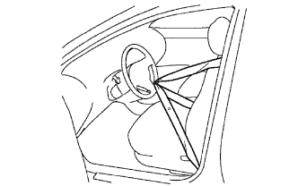
SEPARATE STEERING INTERMEDIATE SHAFT ASSEMBLY NO. 2
-
Hold the steering wheel assembly with the seat belt in order to prevent rotation and damage to the spiral cable.
-
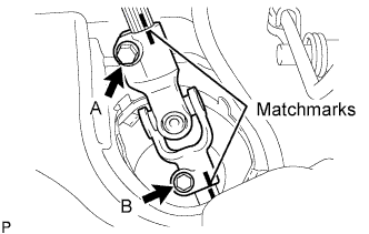
Place matchmarks on the sliding yoke sub-assembly and the intermediate shaft.
-
Loosen bolt A and remove bolt B to separate the sliding yoke sub-assembly.
-
-
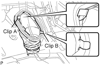
SEPARATE STEERING COLUMN HOLE COVER SUB-ASSEMBLY NO. 1
-
Remove clip A and separate the steering column hole cover from the body.
Note
Do not damage clip B.
-
-
REMOVE FRONT WHEELS
-
DRAIN TRANSAXLE OIL
-
Remove the filler plug and gasket.
-
Remove the drain plug and gasket, and then drain the manual transaxle oil.
-
-
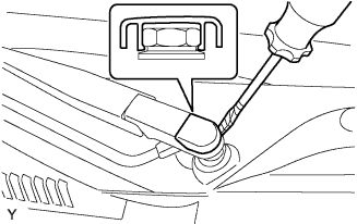
REMOVE FRONT WIPER ARM HEAD CAP
-
Using a screwdriver with its tip wrapped in protective tape, remove the front wiper arm head cap.
-
-
REMOVE FRONT WIPER ARM LH
-
Operate the wiper, then stop the windshield wiper motor assembly in the automatic stop position.
-
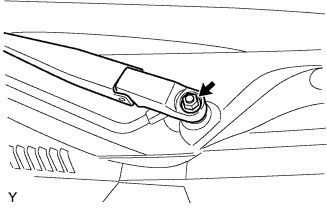
Remove the nut and front wiper main arm.
-
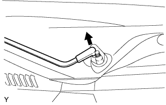
Disengage the meshing of the secondary arm from the front wiper motor and link assembly.
Note
Do not bend the secondary arm when removing it.
-
-
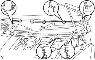
REMOVE HOOD TO COWL TOP SEAL

-
Disengage the 8 clips and remove the hood to cowl top seal.
-
-
REMOVE COWL TOP VENTILATOR LOUVER LH
-
Remove the clip.
-
Disengage the 9 claws and remove the cowl top ventilator louver LH.
-
Disconnect the washer hose.
-
-
REMOVE COWL TOP VENTILATOR LOUVER RH

-
Remove the clip.
-
Disengage the 8 claws and remove the cowl top ventilator louver RH.
-
Disconnect the washer hose.
-
-
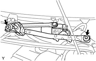
REMOVE FRONT WIPER MOTOR AND LINK ASSEMBLY
-
Remove the 2 bolts.
-
Disconnect the connector and remove the front wiper motor and link assembly.
-
-
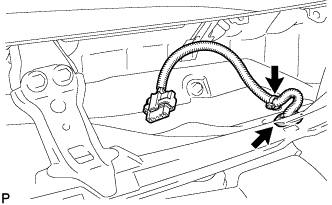
REMOVE COWL TOP PANEL OUTER
-
Remove the clamp of the wire harness.
-
Remove the grommet of the wire harness.
-
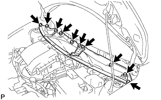
Remove the 10 bolts and cowl top panel.
-
-
REMOVE BATTERY
-
Loosen the nut and disconnect the battery positive terminal.
-
Remove the bolt and battery clamp.
-
Remove the battery.
-
-
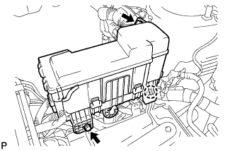
SEPARATE ENGINE ROOM RELAY BLOCK
-
Remove the 2 bolts.
-
Disengage the claw and separate the engine room relay block.
-
Provisionally set the relay block to the hood support rod.
-
-
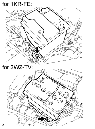
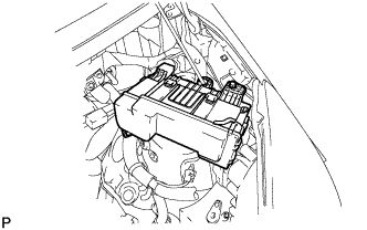
REMOVE BATTERY HOLD DOWN CLAMP
-
Disengage the 2 wire harness clamps.
-
Remove the 3 bolts and battery clamp.
-
-
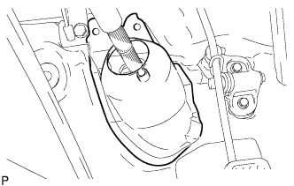
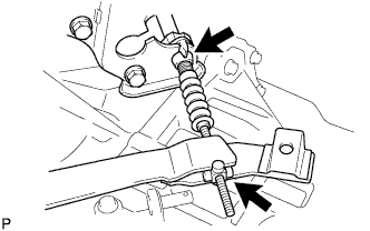
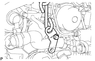
REMOVE CLUTCH RELEASE FORK RETURN TENSION SPRING
-
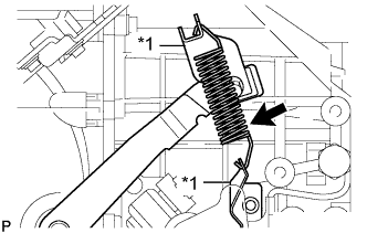
Text in Illustration *1 Spring Hanger Remove the clutch release fork return tension spring from the spring hanger.
Note
-
If there is any rust or deformation in the tension spring, replace it.
-
If there is any damage in the tension spring damper, replace it.
-
-
-
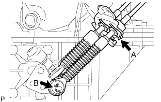
SEPARATE TRANSMISSION CONTROL CABLE ASSEMBLY
-
Remove the clip A and clip B, then separate the transmission shift cable from the manual transaxle.
-
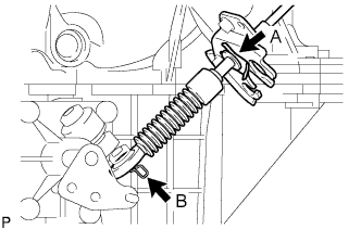
Remove the clip A and clip B, then separate the transmission select cable from the manual transaxle.
-
-
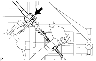
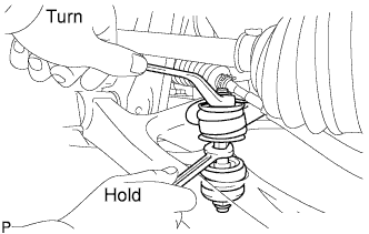
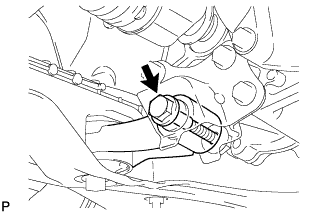
SEPARATE CLUTCH RELEASE CABLE ASSEMBLY
-
Turn and loosen the clutch release cable adjusting nut.
-
Separate the clutch release cable from the manual transaxle.
-
-
DISCONNECT WIRING HARNESS CLAMP BRACKET
-
Disconnect the back-up light switch connector.
-
Disconnect the oxygen sensor connector.
-
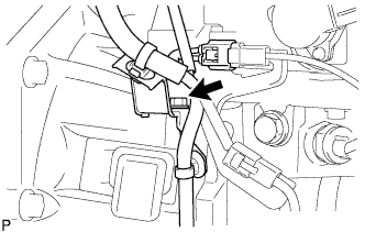
Remove the bolt and disconnect the wiring harness bracket.
-
-
DISCONNECT ENGINE WIRE NO.3
-
Remove the 2 bolts and disconnect the engine wire No. 3 (ground cable).
-
-
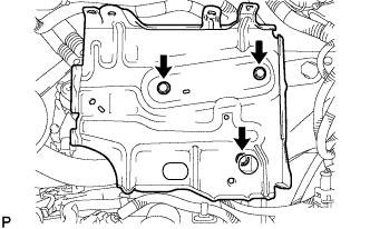
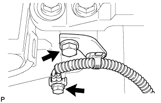
REMOVE FLYWHEEL HOUSING UNDER COVER
-
Remove the 3 bolts and flywheel housing under cover.
-
-
REMOVE STARTER ASSEMBLY
-
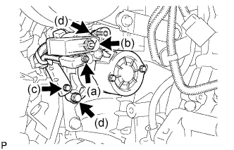
Open the terminal cap, remove the nut and disconnect the wire harness from terminal 50.
-
Open the terminal cap, remove the nut and disconnect the wire harness from terminal 30.
-
Remove the bolt, and wire harness clamp.
-
Remove the 2 bolts, and the starter.
-
-
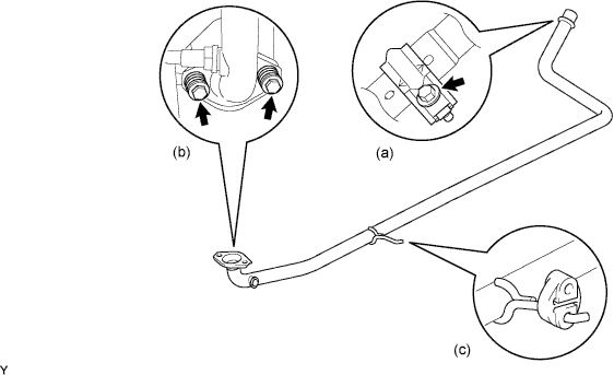
REMOVE EXHAUST PIPE ASSEMBLY FRONT
-
Remove the bolt and clamp.
-
Remove the 2 bolts, 2 compression springs and exhaust pipe gasket.
-
Remove the exhaust pipe No.4 support and exhaust front pipe assembly.
-
-
SEPARATE SPEED SENSOR FRONT LH
-
SEPARATE SPEED SENSOR FRONT RH
Tech Tips
The separation procedure for the RH side is the same as that for the LH side.
-
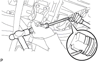
REMOVE FRONT AXLE SHAFT LH NUT
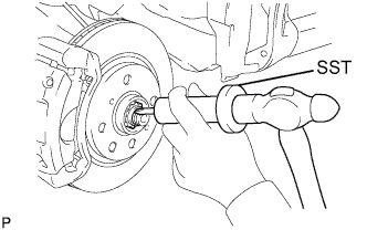
-
Using SST and a hammer, release the staked part of the front axle hub nut.
- SST
- 09930-00010
Note
Release the staked part of the lock nut completely. Otherwise, the screw of the drive shaft may be damaged.
-
While applying the brake, remove the front axle hub nut.
-
-
REMOVE FRONT AXLE SHAFT RH NUT
Tech Tips
The removal procedure for the RH side is the same as that for the LH side.
-
SEPARATE TIE ROD END SUB-ASSEMBLY LH
-
Remove the cotter pin and castle nut.
-
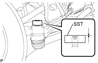
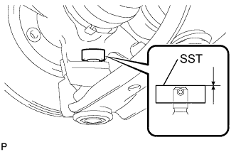
Install SST (spacer B) to the threaded section of the tie rod end.
- SST
- 09960-20010 ( 09961-02060 )
Tech Tips
Make sure the upper ends of the threaded section of the tie rod end and SST (spacer B) are aligned.
-
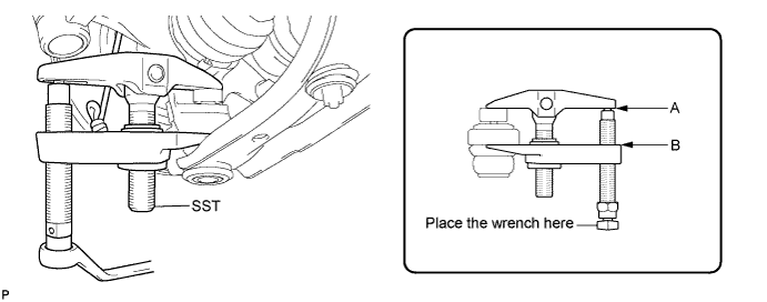
Using SST, separate the tie rod end from the front axle assembly.
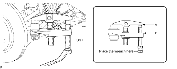
- SST
- 09960-20010 ( 09961-02010 )
Note
-
Make sure to tie the string of SST to the vehicle to prevent SST from dropping.
-
Install SST so that A and B are parallel.
-
Be sure to place the wrench on the part indicated in the illustration.
-
Do not damage the ball joint dust cover.
-
Do not damage the front disc brake dust cover.
-
-
SEPARATE TIE ROD END SUB-ASSEMBLY RH
Tech Tips
The separation procedure for the RH side is the same as that for the LH side.
-
REMOVE FRONT STABILIZER BAR
-
Hold the bolt with a spanner (10 mm) and remove the nut.
-
Remove the 2 cushion retainers and 2 cushions, and separate the front stabilizer bar.
-
-
SEPARATE FRONT SUSPENSION ARM SUB-ASSEMBLY LOWER NO. 1 LH
-
Remove the clip and castle nut.
-
Install SST (spacer B) to the threaded section of the lower ball joint.
- SST
- 09960-20010 ( 09961-02060 )
Tech Tips
Make sure the upper ends of the threaded section of the lower ball joint and SST (spacer B) are aligned.
-
Using SST, separate the lower arm.
- SST
- 09960-20010 ( 09961-02010 )
Note
-
Make sure to tie the string of SST to the vehicle to prevent SST from dropping.
-
Install SST so that A and B are parallel.
-
Be sure to place the wrench on the part indicated in the illustration.
-
Do not damage the lower ball joint dust cover.
-
Do not damage the drive shaft outboard joint boots.
-
Do not damage the front disc brake dust cover.
-
-
SEPARATE FRONT SUSPENSION ARM SUB-ASSEMBLY LOWER NO.1 RH
Tech Tips
The separation procedure for the RH side is the same as that for the LH side.
-
REMOVE FRONT AXLE ASSEMBLY LH
-
Using a plastic hammer, tap the end of the front drive shaft assembly and disengage the fitting between the front drive shaft assembly and front axle assembly.
Tech Tips
If it is difficult to disengage the fitting, tap the end of the front drive shaft assembly with a brass bar and hammer.
-
Push the front axle assembly out of the vehicle to remove the front drive shaft assembly from the front axle assembly.
Note
-
Do not push the front axle assembly further out of the vehicle than is necessary.
-
Do not damage the front axle outboard joint boot.
-
Do not damage the speed sensor rotor.
-
Hang the front drive shaft assembly down with a piece of string or equivalent.
-
When removing the drive shaft, do not hit the sensor with it.
-
-
-
REMOVE FRONT AXLE ASSEMBLY RH
Tech Tips
The removal procedure for the RH side is the same as that for the LH side.
-
REMOVE FRONT DRIVE SHAFT ASSEMBLY LH
-
Using a screwdriver and hammer, remove the front drive shaft assembly.
Note
-
Do not damage the oil seal or the boot.
-
Do not drop the drive shaft assembly.
-
-
-
REMOVE FRONT DRIVE SHAFT ASSEMBLY RH
Tech Tips
The removal procedure for the RH side is the same as that for the LH side.
-
SUSPEND ENGINE ASSEMBLY
-
for 1KR-FE:
-
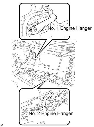
Install the No. 1 and No. 2 engine hangers, oriented in the correct directions.
Part No. No. 1 engine hanger : 12281 - 40030 No. 2 engine hanger : 12282 - 40010 Bolt 91671 - 80820 - Torque:
- 28 N*m { 286 kgf*cm, 21 ft.*lbf }
-
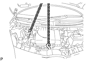
Attach the engine sling device to the engine hangers.
CAUTION:
Do not hang the engine by hooking the chain to any other parts.
-
-
for 2WZ-TV:
-
Attach the engine sling device and suspend the engine with the chain block.
-
-
-
REMOVE FRONT SUSPENSION CROSSMEMBER SUB-ASSEMBLY
-
Remove the 3 bolts, then separate the engine mounting control bracket (for 1KR-FE).
-
Remove the bolt, then separate the control rod from the engine mounting control bracket (for 2WZ-TV).
-
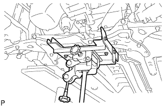
Using a transmission jack, support the front suspension crossmember sub-assembly.
-
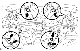
Remove the 6 bolts and the front suspension crossmember sub-assembly.
-
-
SUPPORT MANUAL TRANSAXLE ASSEMBLY
-
Support the manual transaxle with a transmission jack.
-
-
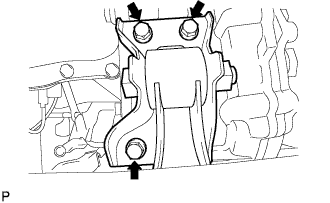
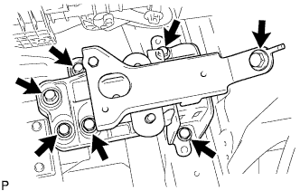
REMOVE ENGINE MOUNTING INSULATOR LH
-
Remove the 7 bolts and engine mounting insulator with the engine mounting bracket.
-
-
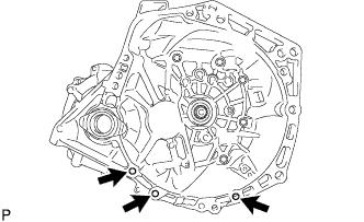
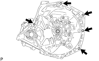
REMOVE MANUAL TRANSAXLE ASSEMBLY
-
Remove the 5 bolts and manual transaxle from the engine.
-