CLUTCH ACTUATOR (for C551A) INSTALLATION

-
INSTALL CLUTCH STROKE SENSOR

-
Apply MP grease to a new O-ring.
-
Install the new O-ring onto the stroke sensor.
-
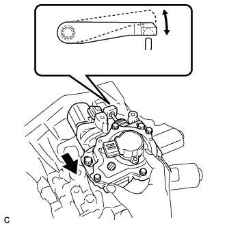
Set the stroke sensor so that the sensor side and the actuator side sensor arms are in the positions shown in the illustration.
-
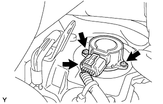
Turn the stroke sensor clockwise and fix it with the 2 screws.
- Torque:
- 2.0 N*m { 20 kgf*cm, 18 in.*lbf }
-
Connect the clutch stroke sensor connector.
-
Install the connector into the clamp bracket.
-
-
CLUTCH POSITION ADJUSTMENT
Note
Perform the following procedure ((a) to(e)) to set a new clutch actuator in the clutch clamp position because it is not originally placed in that position.
Tech Tips
-
The multi-mode manual transmission system has a load controlled clutch cover (adjustment system). The pressure plate moves depending on the wear quantity of the clutch disc lining.
-
When removing or installing any parts related to the multi-mode manual transmission system, move the clutch actuator to the clutch clamp position. This is for normal operation of the load controlled clutch cover (adjustment system).
-
If the clutch position adjustment operation input fails, perform the operation again from step (1) more than 15 seconds after turning the ignition switch to OFF.
Note
Do not depress the brake pedal while performing the clamp position adjustment using an intelligent tester.
-
Connect the clutch stroke sensor connector and motor connector to the clutch actuator.
-
Connect the battery negative terminal.
-
Perform clutch position adjustment (clutch clamp position)
-
Prepare the vehicle:
-
Stop the vehicle.
-
Shift the lever into the N position.
-
Turn the ignition switch to OFF.
-
Apply the parking brake.
-
-
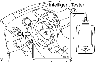
Connect the intelligent tester to the DLC3.
-
Turn the ignition switch to ON.
-
Turn the intelligent tester ON.
-
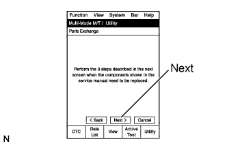
Select the following menu items: Powertrain / Multi-Mode M/T / Utility / Parts Exchange.
-
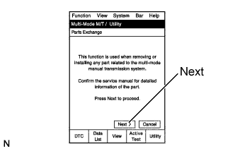
Read the information.
-
Press the Next key.
-
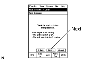
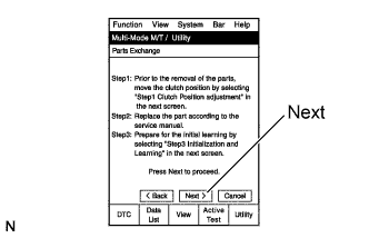
Read the information.
-
After checking the vehicle condition, press the Next key.
-
Read the information.
-
Press the Next key.
-
Read the information.
-
Press the Next key.
-
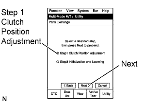
On the Multi-Mode M/T / Utility screen, select Step 1 Clutch Position Adjustment (Clamp Position Adjustment).
-
Press the Next key.
-
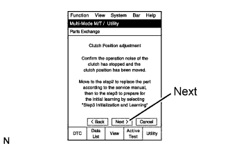
Read the information.
-
Press the Next key.
-
Complete Clutch Position Adjustment.
-
Turn the intelligent tester OFF.
-
Turn the ignition switch to OFF.
-
-
Disconnect the battery negative terminal.
-
Disconnect the clutch stroke sensor connector and motor connector.
-
-
INSTALL CLUTCH ACTUATOR ASSEMBLY
-
Apply grease to the clutch release lever.
-
Set the clutch actuator to the transaxle and provisionally tighten the 3 bolts.
Note
Keep the clearance between the bolt head and actuator flange.
-
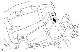
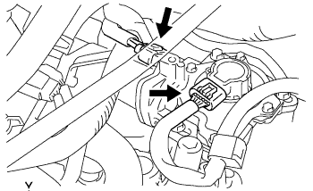
Move the clutch actuator through the bolt hole in the direction indicated by the arrow in the illustration.
-
Check that the clutch release lever moves smoothly in the direction indicated by the arrow in the illustration.
-
Move the clutch actuator in the direction indicated by the arrow in the illustration until the clutch actuator rod end (rounded part) is fully inserted into the groove.
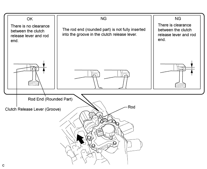
Note
-
Make sure that the clutch actuator rod end is fully inserted into the groove in the clutch release lever.
-
Make sure that the clutch actuator rod end comes into contact with the groove in the clutch release lever so that there is no clearance.
-
-
Tighten the 3 bolts by hand while holding the clutch actuator assembly.
Note
-
Support the clutch actuator assembly until all the 3 bolts are tightened.
-
Make sure that the clutch actuator rod end is fully inserted into the groove in the clutch release lever.
-
Make sure that the clutch actuator rod end comes into contact with the groove in the clutch release lever so that there is no clearance.
-
-
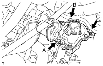
Tighten the 3 bolts to the specified torque in the order A, B, and C, as shown.
- Torque:
- 17 N*m { 173 kgf*cm, 13 ft.*lbf }
-
Connect the clutch stroke sensor connector and motor connector.
-
-
INSTALL BATTERY CLAMP SUB-ASSEMBLY
-
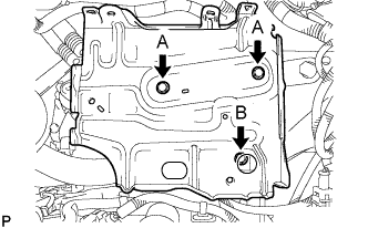
Install the battery clamp with the 3 bolts.
- Torque:
- Bolt A
- 7.4 N*m { 75 kgf*cm, 65 in.*lbf }
- Bolt B
- 17 N*m { 175 kgf*cm, 13 ft.*lbf }
-
Engage the 2 wire harness clamps.
-
-
INSTALL ENGINE ROOM RELAY BLOCK
-
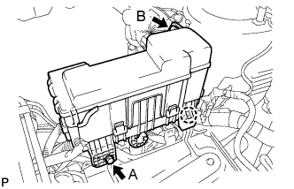
Engage the claw and install the relay block.
-
Install the 2 bolts.
- Torque:
- Bolt A
- 5.4 N*m { 55 kgf*cm, 48 in.*lbf }
- Bolt B
- 8.4 N*m { 85 kgf*cm, 74 in.*lbf }
-
-
INSTALL BATTERY
-
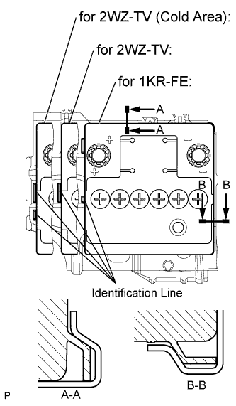
Install the battery onto the battery clamp, as shown in the illustration.
Note
-
The identification line should be seen after installing the battery.
-
The battery clamp should be in contact with the battery after the installation.
-
-
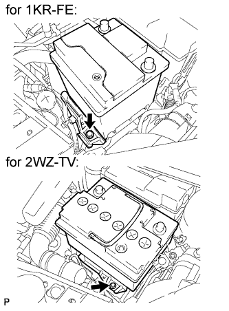
Install the battery clamp with the bolt.
- Torque:
- 15 N*m { 154 kgf*cm, 11 ft.*lbf }
-
Connect the battery positive terminal with the nut.
- Torque:
- 5.4 N*m { 55 kgf*cm, 48 in.*lbf }
-
-
CONNECT CABLE TO NEGATIVE BATTERY TERMINAL
- Torque:
- 5.4 N*m { 55 kgf*cm, 48 in.*lbf }
-
INITIALIZATION OF MULTI-MODE MANUAL TRANSMISSION ECU
-
LEARNING OF MULTI-MODE MANUAL TRANSMISSION SYSTEM
-
SYNCHRONIZATION POSITION CALIBRATION