CLUTCH RELEASE CABLE INSTALLATION

-
INSTALL CLUTCH RELEASE CABLE ASSEMBLY (for LHD)
-
Install the bush to the clutch release cable assembly.
-
Apply lithium soap base glycol grease to the clevis of the clutch pedal.
Text in Illustration 
Lithium soap base glycol grease -
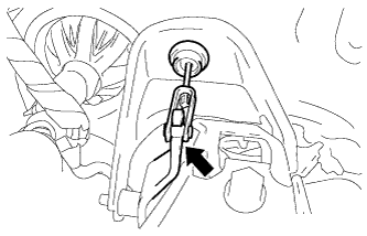
Install the clutch release cable assembly to the clevis of the clutch pedal.
-
Apply lithium soap base glycol grease to the clevis of the clutch release fork lever.
Text in Illustration Lithium soap base glycol grease -
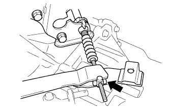
Install the clutch release cable assembly to the manual transaxle assembly.
-
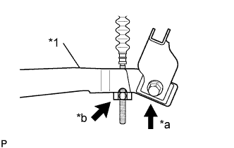
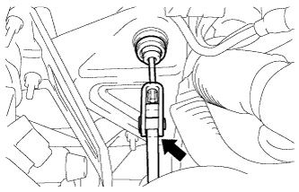
Text in Illustration *1 Clutch Release Fork Lever *a Push *b Turn While holding the clutch release fork lever, turn the cable end clamp and secure it to the flat area of the clutch release fork lever.
-
Move your hand away from the clutch release fork lever and turn the cylinder portion of the cable end clamp and push it into the groove of the clutch release fork lever.
-
Engage the clutch release cable assembly to the 3 clamps and install the grommet into the piercing hole.
-
Depress the clutch pedal a few times to ensure the clutch release cable assembly works smoothly.
Note
Depress the clutch pedal 50 times or more when replacing the clutch release cable assembly with a new one.
-
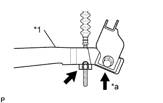
Text in Illustration *1 Clutch Release Fork Lever *a Push Gently push the clutch release fork lever down by hand and make sure that it stops at the position shown in the illustration.
-
-
INSTALL CLUTCH RELEASE CABLE ASSEMBLY (for RHD)
-
Install the bush to the clutch release cable assembly.
-
Apply lithium soap base glycol grease to the clevis of the clutch pedal.
Text in Illustration Lithium soap base glycol grease -
Install the clutch release cable assembly to the clevis of the clutch pedal.
-
Apply lithium soap base glycol grease to the clevis of the clutch release fork lever.
Text in Illustration Lithium soap base glycol grease -
Install the clutch release cable assembly to the manual transaxle assembly.
-
Text in Illustration *1 Clutch Release Fork Lever *a Push *b Turn While holding the clutch release fork lever, turn the cable end clamp and secure it to the flat area of the clutch release fork lever.
-
Move your hand away from the clutch release fork lever and turn the cylinder portion of the cable end clamp and push it into the groove of the clutch release fork lever.
-
Engage the clutch release cable assembly to the clamp and install the grommet into the piercing hole.
-
Depress the clutch pedal a few times to ensure the clutch release cable assembly works smoothly.
Note
Depress the clutch pedal 50 times or more when replacing the clutch release cable assembly with a new one.
-
Text in Illustration *1 Clutch Release Fork Lever *a Push Gently push the clutch release fork lever down by hand and make sure that it stops at the position shown in the illustration.
-
-
INSTALL CLUTCH RELEASE FORK RETURN TENSION SPRING
-
Install the clutch release fork return tension spring to the release fork retracting spring hanger.
-
-
INSPECT AND ADJUST CLUTCH PEDAL SUB-ASSEMBLY
-
Turn up the floor carpet.
-
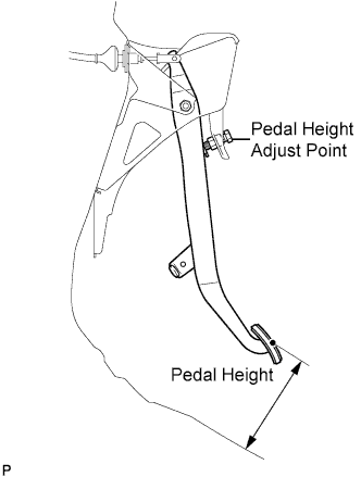
Check whether the pedal height is correct.
Pedal height from floor panel LHD 135 to 145 mm (5.31 to 5.71 in.) RHD 161 to 171 mm (6.34 to 6.74 in.) -
Adjust the pedal height.
-
Loosen the lock nut and turn the stopper bolt until the height is correct.
-
Tighten the lock nut.
- Torque:
- 25 N*m { 250 kgf*cm, 18 ft.*lbf }
-
-
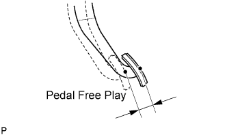
Check that the pedal free play is correct.
-
Depress the pedal until the resistance begins to be felt.
Pedal free play 13 to 23 mm (0.512 to 0.906 in.)
-
-
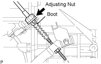
Adjust the pedal free play.
-
Turn the clutch release cable adjusting nut until the pedal free play is correct.
Note
Confirm that the clutch cable boot is installed.
-
After adjusting the pedal free play, check the pedal height.
-
-
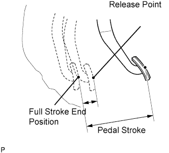
Check the clutch release point.
-
Pull the parking brake lever and install the wheel stopper.
-
Start the engine and allow it to idle.
-
Without depressing the clutch pedal, slowly adjust the shift lever to the reverse position until the gears come into contact with the clutch pedal.
-
Gradually depress the clutch pedal and measure the stroke distance from the point that the gear noise stops (release point) up to the full stroke end position.
Standard distance 20 mm (0.787 in.) or more (from pedal stroke end position to release point) If the distance is not as specified, perform the following operations.
-
Check the pedal height.
-
Check the pedal free play.
-
Check the clutch cover and disc.
-
Check the pedal stroke.
Pedal stroke 148 mm (5.83 in.) -
-
-
-
INSTALL BATTERY CLAMP SUB-ASSEMBLY
-
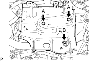
Install the battery clamp sub-assembly with the 3 bolts.
- Torque:
- Bolt A
- 7.4 N*m { 75 kgf*cm, 65 in.*lbf }
- Bolt B
- 17 N*m { 175 kgf*cm, 13 ft.*lbf }
-
-
INSTALL ENGINE ROOM RELAY BLOCK
-
Engage the 3 wire harness clamps.
-
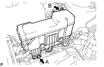
Engage the claw and install the engine room relay block.
-
Install the 2 bolts.
- Torque:
- Bolt A
- 5.4 N*m { 55 kgf*cm, 48 in.*lbf }
- Bolt B
- 8.4 N*m { 85 kgf*cm, 74 in.*lbf }
-
-
INSTALL BATTERY
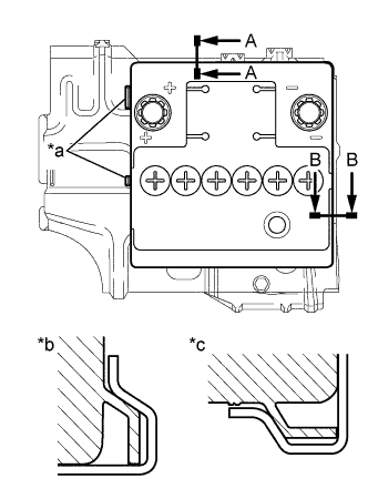
Text in Illustration *a Identification line *b A-A *c B-B
-
Install the battery onto the battery clamp sub-assembly, as shown in the illustration.
Note
-
The identification line should be seen after installing the battery.
-
The battery clamp should be in contact with the battery after the installation.
-
-
Install the battery clamp with the bolt.
- Torque:
- 15 N*m { 154 kgf*cm, 11 ft.*lbf }
-
Connect the battery positive (+) terminal with the nut.
- Torque:
- 5.4 N*m { 55 kgf*cm, 48 in.*lbf }
-
-
INSTALL COWL TOP PANEL OUTER
-
Install the cowl top panel outer with the 10 bolts.
- Torque:
- 9.2 N*m { 94 kgf*cm, 81 in.*lbf }
-
Engage the grommet and install the wire harness.
-
Engage the wire harness clamp.
-
-
INSTALL FRONT NO. 1 VENTILATOR SEAL
-
Install the No. 1 ventilator seal with the 2 clips.
-
-
INSTALL FRONT AIR SHUTTER SEAL RH
-
Install the front air shutter seal RH the 2 clips.
-
-
INSTALL FRONT WIPER MOTOR AND LINK ASSEMBLY
-
INSTALL INSTRUMENT PANEL ASSEMBLY
-
CONNECT CABLE TO NEGATIVE BATTERY TERMINAL
- Torque:
- 5.4 N*m { 55 kgf*cm, 48 in.*lbf }