CLUTCH RELEASE CABLE INSTALLATION

-
INSTALL CLUTCH RELEASE CABLE ASSEMBLY
-
Apply lithium soap base glycol grease to the clevis of the clutch pedal.
-
Install the clutch release cable onto the clevis of the clutch pedal.
-
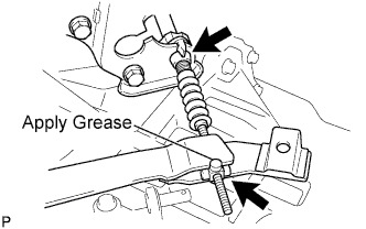
Apply lithium soap base glycol grease to the clevis of the clutch release lever.
-
Install the clutch release cable onto the manual transaxle.
-
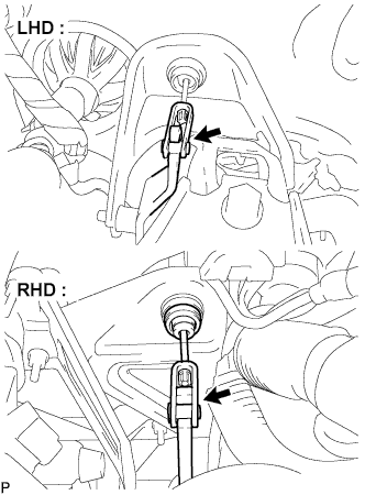
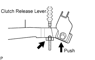
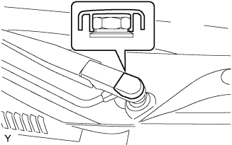
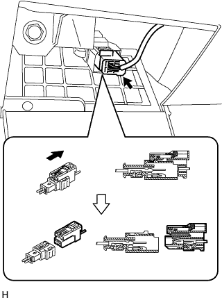
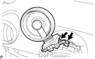
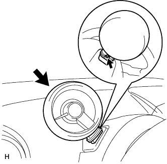
While holding the clutch release lever, turn the cable end clamp and secure it to the flat area of the clutch release lever.
-
Move your hand away from the clutch release lever and turn the cylinder portion of the cable end clamp and push it into the groove of the clutch release lever.
-
LHD:
-
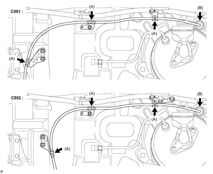
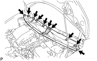
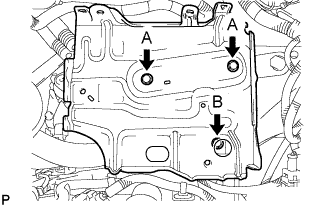
Engage the clutch release cable with the 3 brackets (A) and install the grommet (B) into the piercing hole.
-
-
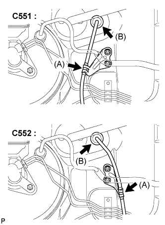
RHD:
-
Engage the clutch release cable with the bracket (A) and install the grommet (B) into the piercing hole.
-
-
Depress the clutch pedal a few times to ensure the clutch release cable works smoothly.
Note
Depress the clutch pedal 50 times or more when replacing the clutch release cable with a new one.
-
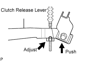
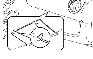
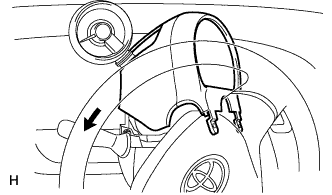
Gently push the clutch release lever down by hand and make sure that it stops at the position shown in the illustration.
-
-
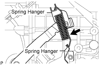
INSTALL CLUTCH RELEASE FORK RETURN TENSION SPRING
-
Install the clutch release fork return tension spring onto the release fork retracting spring hanger.
-
-
INSPECT AND ADJUST CLUTCH PEDAL SUB-ASSEMBLY
-
Turn up the floor carpet.
-
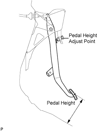
Check whether the pedal height is correct.
Pedal height from floor panel LHD 135 to 145 mm (5.31 to 5.71 in.) RHD 161 to 171 mm (6.34 to 6.74 in.) -
Adjust the pedal height.
-
Loosen the lock nut and turn the stopper bolt until the height is correct.
-
Tighten the lock nut.
- Torque:
- 25 N*m { 250 kgf*cm, 18 ft.*lbf }
-
-
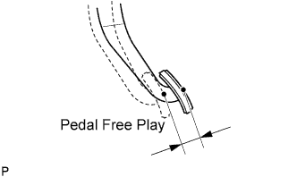
Check that the pedal free play is correct.
-
Depress the pedal until the resistance begins to be felt.
Pedal free play 13 to 23 mm (0.512 to 0.906 in.)
-
-
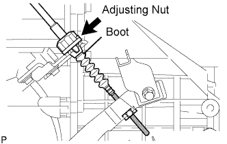
Adjust the pedal free play.
-
Turn the clutch release cable adjusting nut until the pedal free play is correct.
Note
Confirm that the clutch cable boot is installed.
-
After adjusting the pedal free play, check the pedal height.
-
-
Check the clutch release point.
-
Pull the parking brake lever and install the wheel stopper.
-
Start the engine and allow it to idle.
-
Without depressing the clutch pedal, slowly adjust the shift lever to the reverse position until the gears come into contact with the clutch pedal.
-
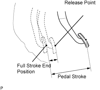
Gradually depress the clutch pedal and measure the stroke distance from the point that the gear noise stops (release point) up to the full stroke end position.
Standard distance 20 mm (0.787 in.) or more (from pedal stroke end position to release point) If the distance is not as specified, perform the following operations.
-
Check the pedal height.
-
Check the pedal free play.
-
Check the clutch cover and disc.
-
Check the pedal stroke.
Pedal stroke 148 mm (5.83 in.) -
-
-
-
INSTALL COWL PANEL SUB-ASSEMBLY
-
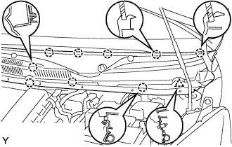
Install the cowl top panel with the 10 bolts.
- Torque:
- 9.2 N*m { 94 kgf*cm, 81 in.*lbf }
-
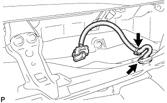
Install the grommet of the wire harness.
-
Install the clamp of the wire harness.
-
-
INSTALL FRONT WIPER MOTOR AND LINK ASSEMBLY
-
Connect the connector.
-
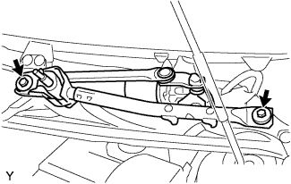
Install the front wiper motor and link assembly with the 2 bolts.
- Torque:
- 13 N*m { 127 kgf*cm, 9 ft.*lbf }
-
-
INSTALL COWL TOP VENTILATOR LOUVER RH
-
Connect the washer hose.
-

Engage the 8 claws and install the cowl top ventilator louver RH.
-
Install the clip.
-
-
INSTALL COWL TOP VENTILATOR LOUVER LH
-
Connect the washer hose.
-
Engage the 9 claws and install the cowl top ventilator louver LH.
-
Install the clip.
-
-
INSTALL HOOD TO COWL TOP SEAL

-
Engage the 8 clips and install the hood to cowl top seal.
-
-
INSTALL FRONT WIPER ARM LH
-
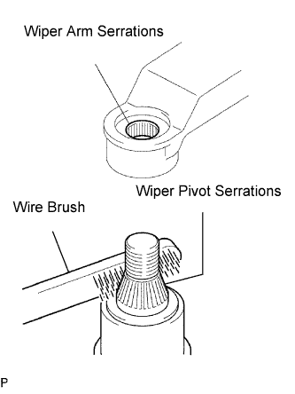
Scrape any metal powder off the serrated part of the wiper arm with a round file or equivalent (when reinstalling).
-
Clean the wiper pivot serrations with a wire brush.
-
Operate the wiper, then stop the windshield wiper motor assembly in the automatic stop position.
-
Provisionally install the front wiper main arm with the nut.
-
Install the front wiper secondary arm onto the front wiper motor and link assembly.
-
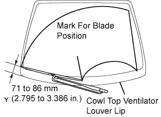
Align the blade tip with the mark on the windshield glass, as shown in the illustration.
-
Tighten the nut of the front wiper main arm.
- Torque:
- 21 N*m { 209 kgf*cm, 15 ft.*lbf }
-
-
INSTALL FRONT WIPER ARM HEAD CAP
-
Engage the claw and install the front wiper arm head cap.
-
-
INSTALL BATTERY HOLD DOWN CLAMP
-
Install the battery clamp with the 3 bolts.
- Torque:
- Bolt A
- 7.4 N*m { 75 kgf*cm, 65 in.*lbf }
- Bolt B
- 17 N*m { 175 kgf*cm, 13 ft.*lbf }
-
Engage the 2 wire harness clamps.
-
-
INSTALL ENGINE ROOM RELAY BLOCK
-
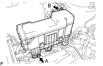
Engage the claw and install the relay block.
-
Install the 2 bolts.
- Torque:
- Bolt A
- 5.4 N*m { 55 kgf*cm, 48 in.*lbf }
- Bolt B
- 8.4 N*m { 85 kgf*cm, 74 in.*lbf }
-
-
INSTALL BATTERY
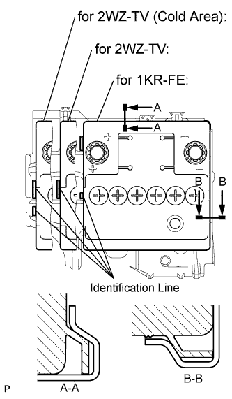
-
Install the battery onto the battery clamp, as shown in the illustration.
Note
-
The identification line should be seen after installing the battery.
-
The battery clamp should be in contact with the battery after the installation.
-
-
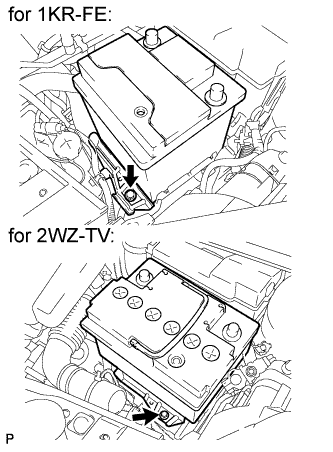
Install the battery clamp with the bolt.
- Torque:
- 15 N*m { 154 kgf*cm, 11 ft.*lbf }
-
Connect the battery positive terminal with the nut.
- Torque:
- 5.4 N*m { 55 kgf*cm, 48 in.*lbf }
-
-
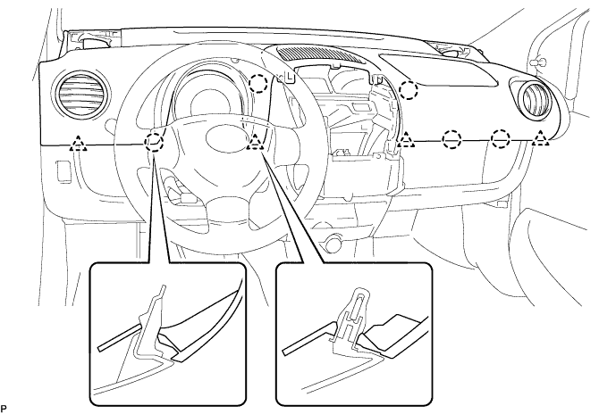
INSTALL INSTRUMENT PANEL ASSEMBLY
-
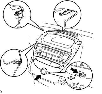
Engage the 4 clips and 5 claws and install the instrument panel assembly.
Note
Make sure that there are no gaps between the instrument panel upper and instrument panel lower panel.
-
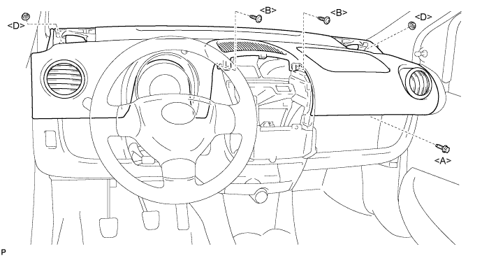
Install the bolt <A>, 2 nuts <D> and 2 screws <B>.
- Torque:
- 18 N*m { 184 kgf*cm, 13 ft.*lbf, for bolt <A> }
- 6.0 N*m { 61 kgf*cm, 53 in.*lbf, for nut <D> }
-
Connect the airbag connector, as shown in the illustration.
-
Engage the 2 claws and close the cover.
-
-
INSTALL INSTRUMENT CLUSTER FINISH PANEL SUB-ASSEMBLY
-
Connect the connectors.
-
Engage the 4 clips and 3 claws and install the instrument cluster finish panel center.
-
Install the screw <B>.
-
Install the control knob.
-
-
INSTALL FRONT NO. 1 SPEAKER ASSEMBLY
-
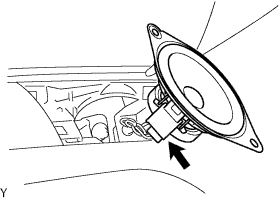
Connect the connector.
-
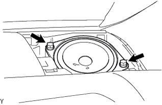
Install the 2 screws.
-
-
INSTALL INSTRUMENT PANEL SPEAKER PANEL SUB-ASSEMBLY NO. 2
-
Engage the 2 claws.
-
-
INSTALL FRONT NO. 1 SPEAKER ASSEMBLY
-
INSTALL INSTRUMENT PANEL SPEAKER PANEL SUB-ASSEMBLY
-
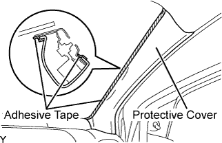
INSTALL FRONT PILLAR GARNISH RH
-
Remove the adhesive tape and protective cover.
-
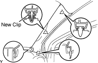
Install a new clip.
-
Engage the 2 claws and 2 clips, and install the front pillar garnish.
-
-
INSTALL FRONT PILLAR GARNISH LH
-
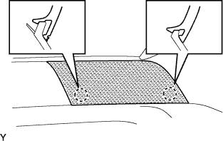
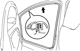
INSTALL FRONT DOOR OPENING TRIM WEATHERSTRIP LH
-
Install the front door opening trim weatherstrip.
-
-
INSTALL FRONT DOOR OPENING TRIM WEATHERSTRIP RH
-
INSTALL TACHOMETER (w/ TACHOMETER)
-
Install the tachometer with the bolt.
- Torque:
- 6.5 N*m { 66 kgf*cm, 58 in.*lbf }
-
Connect the connector.
-
-
INSTALL STEERING COLUMN COVER UPPER
-
Install the steering column cover upper, as shown in the illustration (w/ tachometer).
-
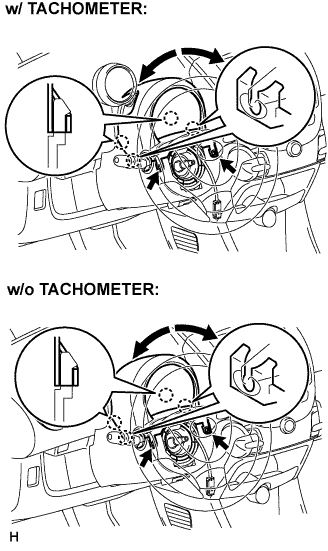
While turning the steering wheel to the right and left, engage the 4 claws and install the steering column cover upper with the 2 screws.
- Torque:
- 2.0 N*m { 20 kgf*cm, 18 in.*lbf }
-
Tighten the screw behind the tachometer (w/ tachometer).
Note
Tighten the screw if the tachometer has been extended and the column cover has been removed.
- Torque:
- 9.0 N*m { 92 kgf*cm, 80 in.*lbf }
-
-
CONNECT CABLE TO NEGATIVE BATTERY TERMINAL
- Torque:
- 5.4 N*m { 55 kgf*cm, 48 in.*lbf }
-
INSPECT SRS WARNING LIGHT