GENERATOR INSTALLATION

-
REMOVE GENERATOR ASSEMBLY (w/o Air Conditioning System)
-
Install the generator bracket No.2 with the 2 bolts to the generator assembly.
- Torque:
- 20 N*m { 204 kgf*cm, 15 ft.*lbf }
-
Using a hexagon socket wrench, install the V-ribbed belt idler assembly No.1 with the bolt to the generator bracket No.2.
- Torque:
- 48 N*m { 490 kgf*cm, 35 ft.*lbf }
-
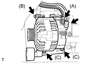
Install the generator assembly with generator bracket No.2 with the 4 bolts.
- Torque:
- Bolt A
- 49 N*m { 500 kgf*cm, 36 ft.*lbf }
- Bolt B
- 44 N*m { 449 kgf*cm, 32 ft.*lbf }
- Bolt C
- 20 N*m { 204 kgf*cm, 15 ft.*lbf }
-
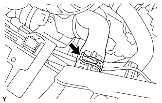
Install the generator wire to terminal B with the nut.
- Torque:
- 16 N*m { 163 kgf*cm, 12 ft.*lbf }
-
Install the terminal cap.
-
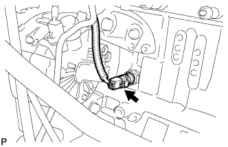
Connect the generator connector.
-
-
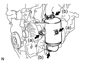
INSTALL GENERATOR ASSEMBLY (w/ Air Conditioning System)
-
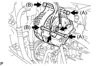
Install the generator assembly with the 4 bolts.
- Torque:
- Bolt A
- 49 N*m { 500 kgf*cm, 36 ft.*lbf }
- Bolt B
- 44 N*m { 449 kgf*cm, 32 ft.*lbf }
-
Install the generator wire to terminal B with the nut.
- Torque:
- 16 N*m { 163 kgf*cm, 12 ft.*lbf }
-
Install the terminal cap.
-
Connect the generator connector.
-
-
CONNECT WIRE HARNESS
-
w/ Air Conditioning System:
-
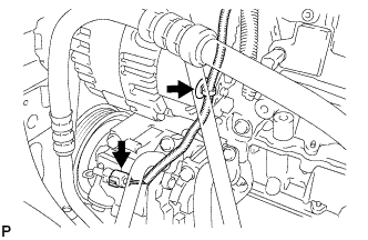
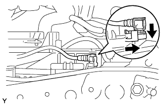
Connect the wire harness to the generator assembly.
-
Connect the compressor connector.
-
-
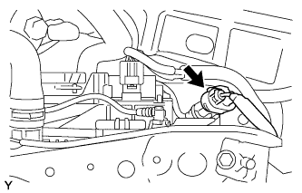
Connect the engine oil pressure switch connector.
-
-
INSTALL STUD BOLT
-
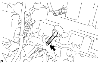
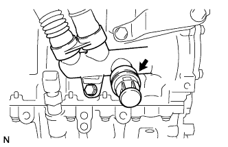
Using a "trox" socket wrench (E7), install the stud bolt.
- Torque:
- 8.0 N*m { 82 kgf*cm, 71 in.*lbf }
-
-
INSTALL OIL LEVEL GAUGE GUIDE
-
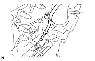
Install 2 new O-rings to the oil level gauge guide.
-
Install the oil level gauge guide with the bolt.
- Torque:
- 8.0 N*m { 82 kgf*cm, 71 in.*lbf }
-
-
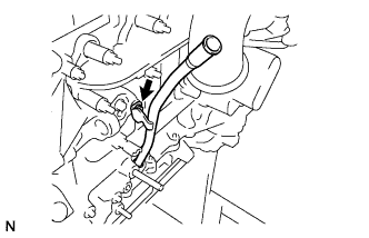
INSTALL OIL LEVEL GAGE SUB-ASSEMBLY
-
Install the oil level gauge.
-
-
INSTALL EXHAUST MANIFOLD CONVERTER SUB-ASSEMBLY
-
Install the converter separator insulator No.1, catalytic converter support bracket, and exhaust manifold converter sub-assembly with the 2 nuts.
-
Temporarily tighten the 2 nuts to the specified torque.
- Torque:
- 4.0 N*m { 41 kgf*cm, 35 in.*lbf }
-
Fully tighten the 2 nuts to the specified torque.
- Torque:
- 20 N*m { 204 kgf*cm, 15 ft.*lbf }
-
-
Install the exhaust manifold converter clamps with the 2 nuts.
- Torque:
- 25 N*m { 255 kgf*cm, 18 ft.*lbf }
-
-
INSTALL MANIFOLD HEAT SHIELD
-
Install the manifold heat shield with the 2 bolts.
- Torque:
- 4.0 N*m { 41 kgf*cm, 35 in.*lbf }
-
-
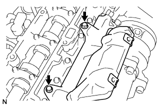
INSTALL TURBO INSULATOR NO.1
-
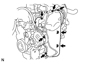
Install the turbo insulator No.1 with the 7 bolts.
- Torque:
- 4.0 N*m { 41 kgf*cm, 35 in.*lbf }
-
-
INSTALL V-RIBBED BELT TENSIONER SUB-ASSEMBLY
-
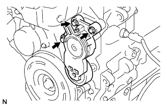
Install the V-ribbed belt tensioner sub-assembly with the 3 bolts.
- Torque:
- 20 N*m { 204 kgf*cm, 15 ft.*lbf }
-
-
INSTALL V-RIBBED BELT
-
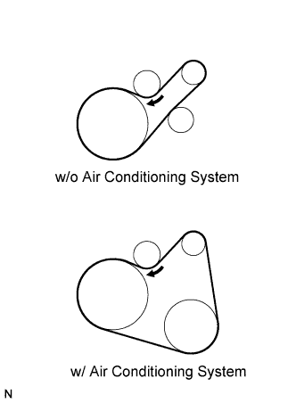
Install the belt.
-
While turning the belt tensioner clockwise, remove the bar.
-
-
INSTALL RADIATOR ASSEMBLY
-
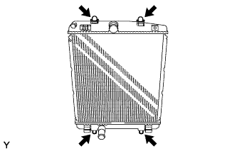
Install the 2 radiator support cushions and 2 grommets to the radiator assembly.
-
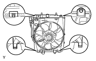
Install the fan assembly to the radiator assembly, with the claws and tighten the bolt.
- Torque:
- 7.5 N*m { 76 kgf*cm, 66 in.*lbf }
-
-
INSTALL FRONT CROSS MEMBER SUB-ASSEMBLY
-
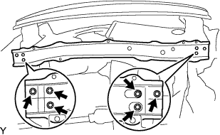
Install the front cross member sub-assembly with the 6 bolts.
- Torque:
- 5.5 N*m { 56 kgf*cm, 49 in.*lbf }
-
-
CONNECT CONDENSER ASSEMBLY (w/ Air Conditioning System)
-
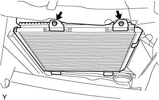
Install the radiator assembly with the 2 bolts.
- Torque:
- 9.8 N*m { 100 kgf*cm, 87 in.*lbf }
-
-
CONNECT RADIATOR HOSE NO.2
-
Connect the radiator hose No.2 with a new clamp.
-
-
CONNECT RADIATOR HOSE
-
Connect the radiator hose with a new clamp.
-
-
CONNECT WATER BY-PASS HOSE
-
Connect the water by-pass hose with a new hose clip.
-
-
CONNECT RESISTOR CONNECTORS (w/ Air Conditioning System)
-
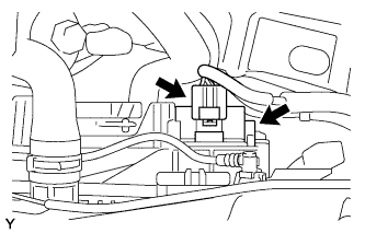
Connect the 2 resistor connectors.
-
-
CONNECT COOLING FAN MOTOR CONNECTOR
-
Connect the cooling fan motor connector.
-
-
ADD ENGINE COOLANT
-
Install the drain plug with an O-ring and a new clip.
-
Connect the radiator hose No.2.
-
Pour engine coolant into the reserve tank assembly.
Capacity 4.0 to 4.4 L Note
Do not substitute water for engine coolant.
Tech Tips
-
Use of improper engine coolant may damage the engine coolant system.
-
Use only Premium Long Life Coolant for 1WZ and 2WZ-TV. Pre-mixed. Green. or similar high quality ethylene glycol based non-silicate, non-amine, non-nitrite, and non-borate engine coolant with long-life hybrid organic acid technology (coolant with long-life hybrid organic acid technology consists of a combination of low phosphates and organic acids).
-
-
Check the engine coolant level inside the radiator assembly by pressing the inlet and outlet radiator hoses several times by hand. If the engine coolant level goes down, add engine coolant.
-
Connect the water by-pass hose with the hose clamp.
Tech Tips
Connect the water by-pass hose, when the fluid flows clean and without air bubbles.
-
Slowly pour engine coolant into the radiator reservoir until it reaches the FULL line.
-
Install the reservoir tank cap sub-assembly securely.
-
-
CONNECT NEGATIVE BATTERY CABLE
-
Connect the negative battery cable.
- Torque:
- 5.4 N*m { 55 kgf*cm, 48 in.*lbf }
-
-
START THE ENGINE
-
CHECK FOR ENGINE COOLANT LEAKS
-
Start the engine.
-
Maintain the engine speed at 1,500 rpm until the first cooling cycle (cooling fan on).
-
Stop the engine and wait for cool down.
-
If necessary top up the level to the maximum mark.
-
-
INSTALL SUPPORT LH SUB-ASSEMBLY
-
INSTALL SUPPORT RH SUB-ASSEMBLY
-
INSTALL FRONT BUMPER COVER
-
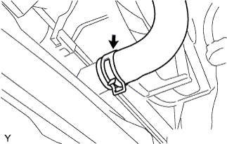
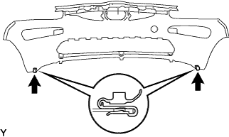
Install the 2 clips.
-
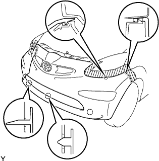
Engage the 13 claws and install the front bumper cover.
-
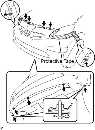
Tighten the 3 bolts and 5 screws.
-
Install the 3 clips.
-
Remove the protective tape.
-
-
INSTALL ENGINE UNDER COVER
-
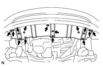
Install the engine under cover with the 5 screws.
-
Install the 9 bolts.
-
-
INSTALL ENGINE COVER
-
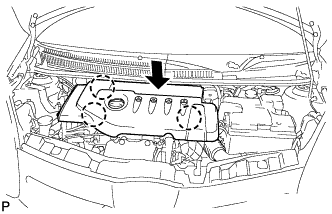
Align the 3 claws to install the engine cover.
-