CLUTCH PEDAL INSTALLATION

-
INSTALL CLUTCH PEDAL SUB-ASSEMBLY (for LHD)
-
Install the pedal pad onto the pedal.
-
Apply lithium soap base glycol grease to the 2 bushes and collar.
-
Install the 2 bushes and collar onto the clutch pedal.
-
Apply lithium soap base glycol grease to the 2 bushes and collar.
-
Install the 2 bushes and collar onto the brake pedal.
-
Install the clutch pedal and brake pedal onto the brake pedal support.
-
Using a 13 mm socket wrench, install the nut and bolt.
- Torque:
- 22 N*m { 224 kgf*cm, 16 ft.*lbf }
-
-
INSTALL CLUTCH PEDAL SUB-ASSEMBLY (for RHD)
-
Install the pedal pad onto the pedal.
-
Apply lithium soap base glycol grease to the 2 bushes and collar.
-
Install the 2 bushes and collar onto the clutch pedal.
-
Install the clutch pedal onto the clutch pedal support.
-
Using a 13 mm socket wrench, install the nut and bolt.
- Torque:
- 22 N*m { 224 kgf*cm, 16 ft.*lbf }
-
-
INSTALL CLUTCH RELEASE CABLE GROMMET
-
Install the grommet onto the pedal support.
-
-
INSTALL BRAKE PEDAL SUPPORT SUB-ASSEMBLY (for LHD)
-
Install the nut onto the pedal support.
-
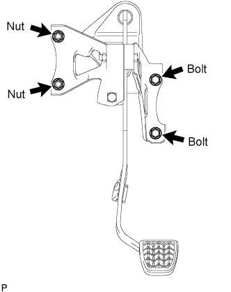
Install the pedal support with the 2 bolts and 4 nuts.
- Torque:
- Nut
- 31 N*m { 311 kgf*cm, 22 ft.*lbf }
- Nut (from VIN VF7PM8HTC89700129)
- 16 N*m { 163 kgf*cm, 12 ft.*lbf }
- Bolt A
- 24 N*m { 241 kgf*cm, 17 ft.*lbf }
- Bolt B
- 14 N*m { 143 kgf*cm, 10 ft.*lbf }
-
Engage the wire harness clamp to the stud bolt.
-
Engage the 2 wire harness clamps to the pedal support.
-
-
INSTALL MASTER CYLINDER PUSH ROD CLEVIS (for LHD)
-
Apply lithium soap base glycol grease to the push rod pin.
-
Install the push rod clevis with the push rod pin and clip.
-
-
INSTALL CLUTCH PEDAL SUPPORT SUB-ASSEMBLY (for RHD)
-
Install the pedal support with the 2 bolts and 2 nuts.
- Torque:
- Nut
- 19 N*m { 195 kgf*cm, 14 ft.*lbf }
- Nut (from VIN VF7PM8HTC89700129)
- 16 N*m { 163 kgf*cm, 12 ft.*lbf }
- Bolt
- 19 N*m { 195 kgf*cm, 14 ft.*lbf }
-
-
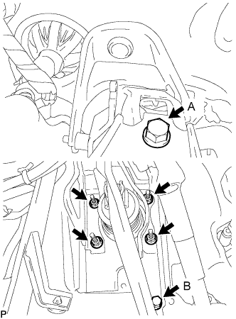
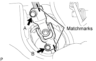
INSTALL NO. 2 STEERING INTERMEDIATE SHAFT ASSEMBLY (for RHD)
-
Align the matchmarks and install steering intermediate shaft assembly No. 2 onto the steering gear sub-assembly with bolt B.
- Torque:
- 35 N*m { 360 kgf*cm, 26 ft.*lbf }
-
Tighten bolt A.
- Torque:
- 35 N*m { 360 kgf*cm, 26 ft.*lbf }
-
Release the seat belt from the steering wheel.
-
-
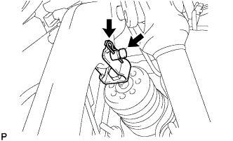
INSTALL CLUTCH RELEASE CABLE ASSEMBLY
-
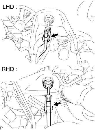
Apply lithium soap glycol grease to the clevis of the clutch pedal.
-
Install the clutch release cable onto the clevis of the clutch pedal.
-
-
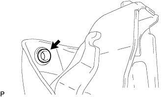
INSTALL CLUTCH SWITCH ASSEMBLY (for 1KR-FE)
-
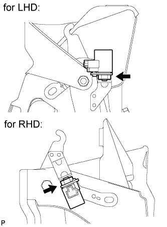
Install the clutch switch with the nut.
- Torque:
- 16 N*m { 160 kgf*cm, 12 ft.*lbf }
Note
Insert the protrusion of the clutch switch into the hole in the pedal support.
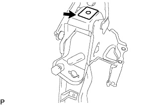
-
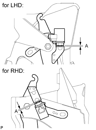
With the clutch pedal released, check gap A of the clutch switch, as shown in the illustration.
Clutch switch clearance A 0.5 to 3.0 mm (0.0197 to 0.118 in.) If gap A is not as specified, adjust the clutch pedal height Click here.
-
Connect the clutch switch connector.
-
-
INSTALL STOP LIGHT SWITCH ASSEMBLY (for LHD)
-
Install a new stop light switch mounting adjuster onto the brake pedal support.
-
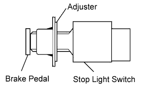
Insert the stop light switch into the adjuster until it slightly touches the brake pedal.
Note
Do not depress the brake pedal.
-

Make a quarter turn clockwise to install the stop light switch.
Note
Do not depress the brake pedal.
Tech Tips
The turning torque for installing the stop light switch:
- Torque:
- 1.5 N*m { 15 kgf*cm, 13 in.*lbf, or less }
-
Check the stop light switch clearance.
Stop light switch clearance 0.5 to 2.6 mm (0.0197 to 0.102 in.) -
Connect the connector to the stop light switch.
-
-
INSPECT AND ADJUST CLUTCH PEDAL
-
Turn up the floor carpet.
-
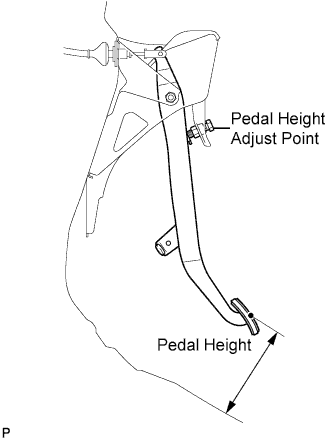
Check whether the pedal height is correct.
Pedal height from floor panel LHD 135 to 145 mm (5.31 to 5.71 in.) RHD 161 to 171 mm (6.34 to 6.74 in.) -
Adjust the pedal height.
-
Loosen the lock nut and turn the stopper bolt until the height is correct.
-
Tighten the lock nut.
- Torque:
- 25 N*m { 250 kgf*cm, 18 ft.*lbf }
-
-
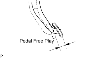
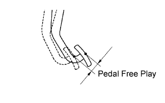
Check that the pedal free play is correct.
-
Depress the pedal until the resistance begins to be felt.
Pedal free play 13 to 23 mm (0.512 to 0.906 in.)
-
-
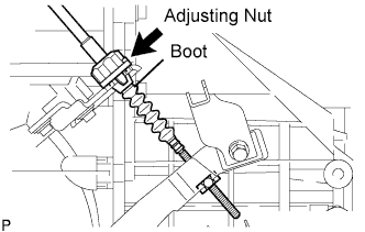
Adjust the pedal free play.
-
Turn the clutch release cable adjusting nut until the pedal free play is correct.
Note
Confirm that the clutch cable boot is installed.
-
After adjusting the pedal free play, check the pedal height.
-
-
Check the clutch release point.
-
Pull the parking brake lever and install the wheel stopper.
-
Start the engine and allow it to idle.
-
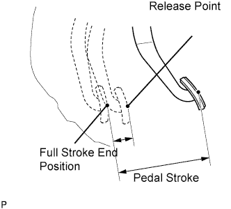
Without depressing the clutch pedal, slowly adjust the shift lever to the reverse position until the gears come into contact with the clutch pedal.
-
Gradually depress the clutch pedal and measure the stroke distance from the point that the gear noise stops (release point) up to the full stroke end position.
Standard distance 20 mm (0.787 in.) or more (from pedal stroke end position to release point) If the distance is not as specified, perform the following operations.
-
Check the pedal height.
-
Check the pedal free play.
-
Check the clutch cover and disc.
-
Check the pedal stroke.
Pedal stroke 148 mm (5.83 in.) -
-
-
-
INSPECT AND ADJUST BRAKE PEDAL (for LHD)
-
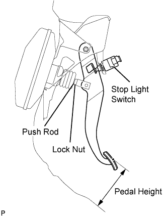
Inspect the brake pedal height.
Pedal height from floor Steering Position Standard for LHD 135.8 to 145.8 mm (5.346 to 5.740 in.) for RHD 121.6 to 131.6 mm (4.787 to 5.181 in.) If the pedal height is incorrect, adjust it.
-
Adjust the brake pedal height.
-
Disconnect the connector from the stop light switch.
-
Turn the stop light switch counterclockwise, and remove the stop light switch.
-
Loosen the push rod lock nut.
-
Adjust the pedal height by turning the pedal push rod.
-
Tighten the push rod lock nut.
- Torque:
- 22 N*m { 224 kgf*cm, 16 ft.*lbf }
-
Insert the stop light switch into the adjuster until it slightly touches the brake pedal.
Note
Do not depress the brake pedal.
-
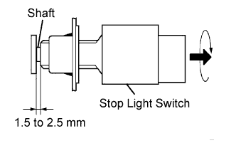
Make a quarter turn clockwise to install the stop light switch.
Note
Do not depress the brake pedal.
Tech Tips
The turning torque for installing the stop light switch:
- Torque:
- 1.5 N*m { 15 kgf*cm, 13 in.*lbf, or less }
-
Check the stop light switch clearance.
Stop light switch clearance 1.5 to 2.5 mm (0.059 to 0.098 in.) -
Connect the connector to the stop light switch.
-
-
Inspect the brake pedal free play.
-
Stop the engine and depress the brake pedal several times until there is no more vacuum left in the booster.
-
Push in the pedal until slight resistance is felt. Measure the distance as shown.
Pedal free play 1.0 to 6.0 mm (0.039 to 0.236 in.) If incorrect, troubleshoot the brake system.
-
-
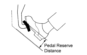
Inspect the brake pedal reserve distance.
-
Release the parking brake lever. With the engine running, depress the pedal and measure the pedal reserve distance as shown.
Pedal reserve distance from floor Specification Condition Standard for 1KR-FE for LHD 490 N (50 kgf, 110.2 lbf) More than 84 mm (3.31 in.) for RHD More than 77 mm (3.03 in.) for 2WZ-TV for LHD More than 79 mm (3.11 in.) for RHD More than 71 mm (2.80 in.) If incorrect, troubleshoot the brake system.
-
-
-
INSTALL LOWER INSTRUMENT PANEL ASSEMBLY
-
Install the lower instrument panel Click here.
-