CLUTCH RELEASE CABLE REMOVAL

-
DISCONNECT CABLE FROM NEGATIVE BATTERY TERMINAL
Wait for at least 90 seconds after disconnecting the cable to prevent the airbag from working.
-
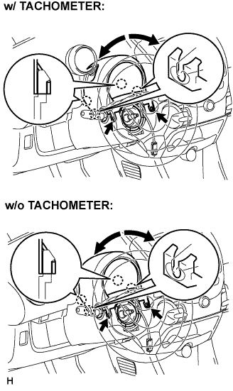
REMOVE STEERING COLUMN COVER UPPER
-
Remove the 2 screws while turning the steering wheel to the right and left.
-
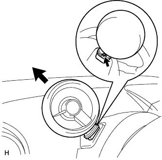
Disengage the 4 claws and remove the steering column cover upper.
-
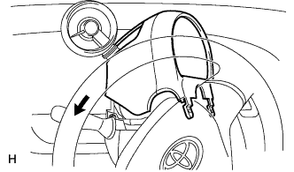
Remove the steering column cover upper, as shown in the illustration (w/ tachometer).
-
If the steering column cover upper is difficult to remove, loosen the screw behind the tachometer, pull up and extend the tachometer, and then remove the steering cover upper (w/ tachometer).
-
-
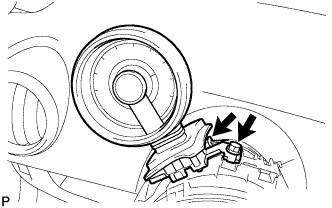
REMOVE TACHOMETER (w/ TACHOMETER)
-
Disconnect the connector.
-
Remove the bolt and tachometer.
-
-
SEPARATE FRONT DOOR OPENING TRIM WEATHERSTRIP LH
-
Separate the front door opening trim weatherstrip LH.
-
-
SEPARATE FRONT DOOR OPENING TRIM WEATHERSTRIP RH
-
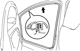
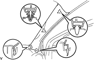
REMOVE FRONT PILLAR GARNISH RH
-
Disengage the 2 clips and 2 claws, and remove the front pillar garnish.
-
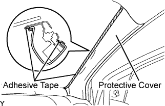
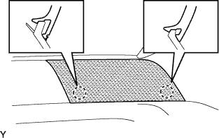
Completely cover the airbag with a piece of cloth or nylon of 700 mm (27.56 in.) x 120 mm (4.72 in.) and fix the ends of the cover with adhesive tape, as shown in the illustration.
Note
Cover the curtain shield airbag with the protective cover as soon as the front pillar garnish is removed.
-
-
REMOVE FRONT PILLAR GARNISH LH
-
REMOVE INSTRUMENT PANEL SPEAKER PANEL SUB-ASSEMBLY NO. 1
-
Disengage the 2 claws.
-
-
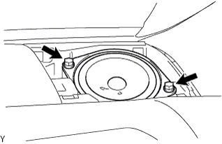
REMOVE FRONT NO. 1 SPEAKER ASSEMBLY
-
Remove the 2 screws.
-
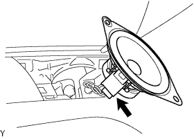
Disconnect the connector.
-
-
REMOVE INSTRUMENT PANEL SPEAKER PANEL SUB-ASSEMBLY
-
REMOVE FRONT NO. 1 SPEAKER ASSEMBLY
-
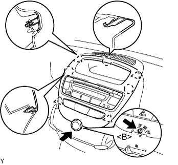
REMOVE INSTRUMENT CLUSTER FINISH PANEL SUB-ASSEMBLY CENTER
-
Remove the control knob.
-
Remove the screw <B>.
-
Disengage the 4 clips and 3 claws and remove the cluster finish panel by pulling it up from underneath.
-
Disconnect the connectors and remove the instrument cluster finish panel center.
-
-
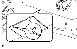
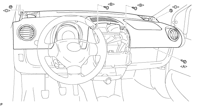
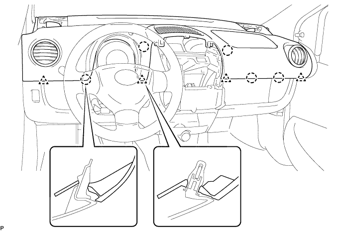
REMOVE INSTRUMENT PANEL ASSEMBLY
-
Disengage the 2 claws and open the cover.
-
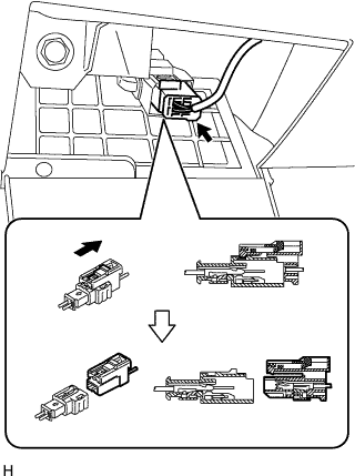
Disconnect the airbag connector, as shown in the illustration.
-
Remove the bolt <A>, 2 nuts <D> and 2 screws <B>.
-
Disengage the 4 clips and 5 claws and remove the instrument panel assembly.
-
-
REMOVE BATTERY
-
Loosen the nut and disconnect the battery positive terminal.
-
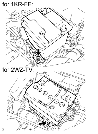
Remove the bolt and battery clamp.
-
Remove the battery.
-
-
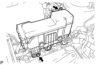
SEPARATE ENGINE ROOM RELAY BLOCK
-
Remove the 2 bolts.
-
Disengage the claw and separate the engine room relay block.
-
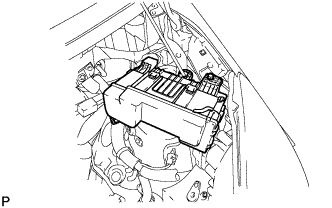
Provisionally set the relay block to the hood support rod.
-
-
REMOVE BATTERY HOLD DOWN CLAMP
-
Disengage the 2 wire harness clamps.
-
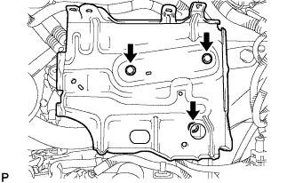
Remove the 3 bolts and battery clamp.
-
-
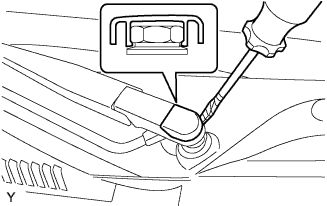
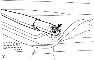
REMOVE FRONT WIPER ARM HEAD CAP
-
Using a screwdriver with its tip wrapped in protective tape, remove the front wiper arm head cap.
-
-
REMOVE FRONT WIPER ARM LH
-
Operate the wiper, then stop the windshield wiper motor assembly in the automatic stop position.
-
Remove the nut and front wiper main arm.
-
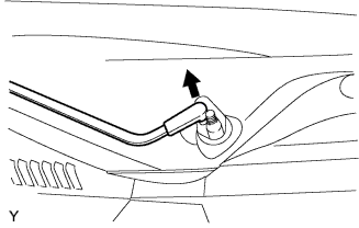
Disengage the meshing of the secondary arm from the front wiper motor and link assembly.
Note
Do not bend the secondary arm when removing it.
-
-
REMOVE HOOD TO COWL TOP SEAL

-
Disengage the 8 clips and remove the hood to cowl top seal.
-
-
REMOVE COWL TOP VENTILATOR LOUVER LH
-
Remove the clip.
-
Disengage the 9 claws and remove the cowl top ventilator louver LH.
-
Disconnect the washer hose.
-
-
REMOVE COWL TOP VENTILATOR LOUVER RH

-
Remove the clip.
-
Disengage the 8 claws and remove the cowl top ventilator louver RH.
-
Disconnect the washer hose.
-
-
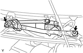
REMOVE FRONT WIPER MOTOR AND LINK ASSEMBLY
-
Remove the 2 bolts.
-
Disconnect the connector and remove the front wiper motor and link assembly.
-
-
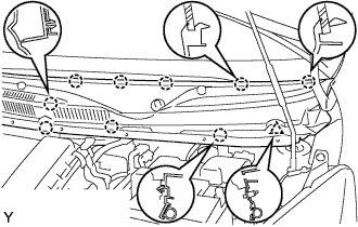
REMOVE COWL PANEL SUB-ASSEMBLY
-
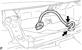
Remove the clamp of the wire harness.
-
Remove the grommet of the wire harness.
-
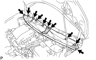
Remove the 10 bolts and cowl top panel.
-
-
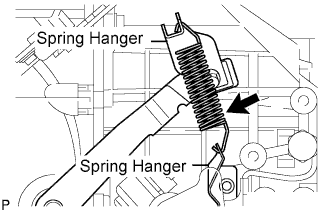
REMOVE CLUTCH RELEASE FORK RETURN TENSION SPRING
-
Remove the clutch release fork return tension spring from the spring hanger.
Note
-
If there is any rust or deformation in the tension spring, replace it.
-
If there is any damage in the tension spring damper, replace it.
-
-
-
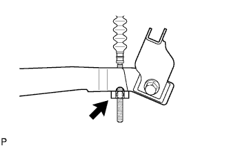
REMOVE CLUTCH RELEASE CABLE ASSEMBLY
-
Turn and loosen the clamp of the cable end.
-
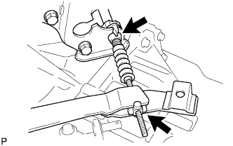
Separate the clutch release cable from the manual transaxle.
-
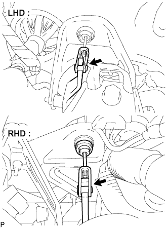
Separate the clutch release cable from the clutch pedal.
-
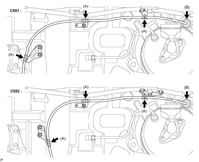
LHD:
-
Disengage the 3 clamps (A) and the grommet (B) of the clutch release cable and remove the clutch release cable.
-
-
RHD:
-
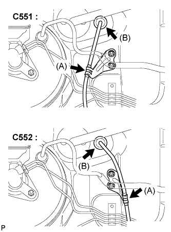
Disengage the clamp (A) and the grommet (B) of the clutch release cable and remove the clutch release cable.
-
-