OIL PUMP INSTALLATION

-
INSTALL CRANK OIL SEAL
-
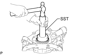
Using SST, tap in a new crank oil seal until its surface is flush with the oil pump case edge.
- SST
- 09505-20010
Note
-
Keep the lip free from foreign matter.
-
Do not tap the oil seal at an angle.
-
-
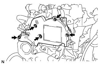
INSTALL OIL PUMP ASSEMBLY
-
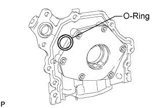
Install a new O-ring to the oil pump assembly.
-
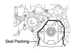
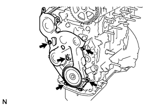
Apply a seal packing to the cylinder block as shown in the illustration.
Seal packing Part No. 0826-00080 or equivalent Note
-
When the contact surfaces are wet, wipe off with an oil-free cloth before applying seal packing.
-
Install the oil pump assembly within 3 minutes after applying packing.
-
-
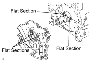
Align the flat sections of the oil pump drive gear with the flat sections located on the crankshaft, and slide the oil pump into place.
-
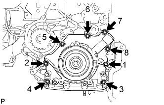
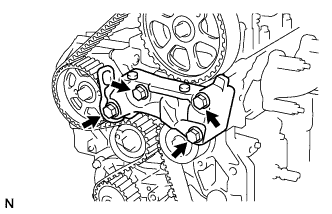
Tighten the 8 bolts in the order shown in the illustration.
- Torque:
- 5.0 N*m { 51 kgf*cm, 44 in.*lbf }
-
Retighten the 8 bolts in the order shown in the illustration.
- Torque:
- 9.0 N*m { 92 kgf*cm, 80 in.*lbf }
-
-
INSTALL OIL STRAINER SUB-ASSEMBLY
-
Install a new gasket to the oil strainer sub-assembly.
-
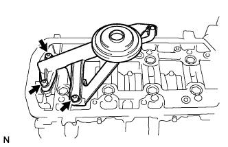
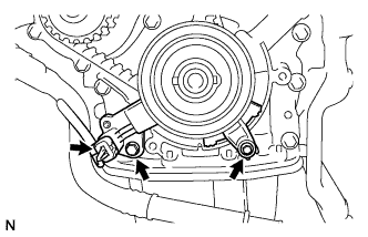
Using a hexagon socket wrench, install the oil strainer sub-assembly with the 3 bolts.
- Torque:
- 7.0 N*m { 71 kgf*cm, 62 in.*lbf }
-
-
INSTALL OIL PAN SUB-ASSEMBLY
-
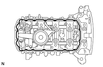
Apply seal packing to the cylinder block as shown in the illustration.
Seal packing Part No. 08826-00080 or equivalent Note
Install the oil pan sub-assembly within 5 minutes after applying packing.
-
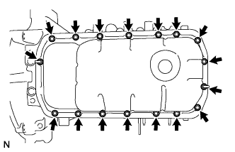
Install the oil pan sub-assembly with the 15 bolts and 2 nuts.
- Torque:
- 10 N*m { 102 kgf*cm, 7 ft.*lbf }
-
-
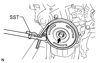
INSTALL CRANKSHAFT PULLEY
-
Install the crankshaft timing pulley and key.
-
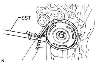
Install crankshaft pulley with the bolt.
-
Using SST, hold the crankshaft.
- SST
- 09330-00021
-
Tighten the bolt.
- Torque:
- 35 N*m { 357 kgf*cm, 22 ft.*lbf }
-
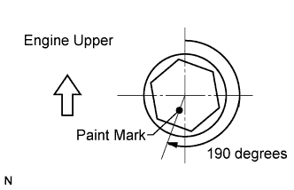
Mark the top surface of the crankshaft pulley bolt with paint.
-
Retighten the bolt by an additional 190 degrees as shown in the illustration.
-
-
INSTALL FLYWHEEL SUB-ASSEMBLY
-
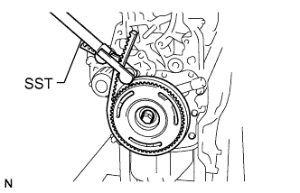
Using SST, hold the crankshaft pulley.
- SST
- 09330-00021
-
Apply adhesive to 2 or 3 threads of the bolt end.
Adhesive Part No. 08833-00070, THREE BOND 1324 or equivalent -
Install the flywheel sub-assembly with the 6 bolts.
- Torque:
- 17 N*m { 173 kgf*cm, 13 ft.*lbf }
Note
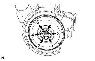
Tighten the bolts in the order shown in the illustration.
-
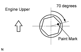
Mark the top surfaces of the flywheel bolts with paint.
-
Retighten the bolts by an additional 70 degrees as shown in the illustration.
-
-
REMOVE CRANKSHAFT PULLEY
-
Using SST, hold the crankshaft pulley.
- SST
- 09330-00021
-
Remove the bolt and crankshaft pulley.
-
-
INSTALL CLUTCH DISC ASSEMBLY
-
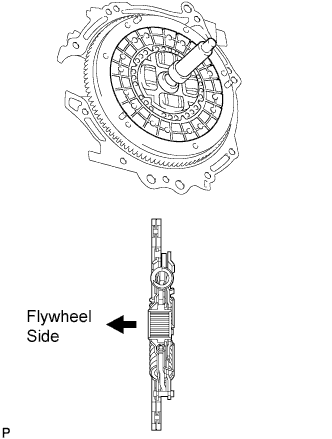
Insert SST into the clutch disc, and then insert them into the flywheel.
- SST
- 09301-00131
Note
Do not insert the clutch disc in the wrong direction.
-
-
INSTALL CLUTCH COVER ASSEMBLY
-
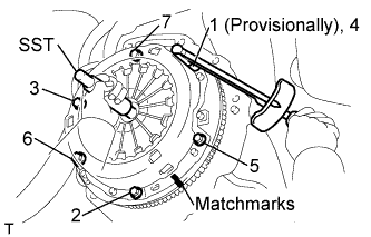
Align the matchmark on the clutch cover with the one on the flywheel.
-
Tighten the 6 bolts uniformly in the order shown in the illustration, starting with the bolt located near the knock pin on the top.
- Torque:
- 19 N*m { 195 kgf*cm, 14 ft.*lbf }
Tech Tips
After checking that the disc is in the center, gently move SST up and down, right and left to tighten the bolts.
- SST
- 09301-00131
-
-
INSTALL MANUAL TRANSAXLE ASSEMBLY
-
Align the input shaft with the clutch disc and install the manual transaxle onto the engine.
-
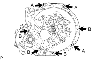
Install the 7 bolts.
- Torque:
- 40 N*m { 408 kgf*cm, 30 ft.*lbf }
Tech Tips
-
Install 3 A bolts from the transaxle side.
-
Install 4 B bolts from the engine side.
-
-
INSTALL STARTER ASSEMBLY
-
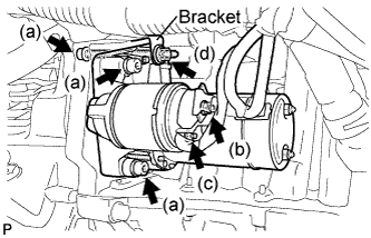
Using a hexagon wrench (6 mm), install the starter with the 3 bolts.
- Torque:
- 20 N*m { 204 kgf*cm, 15 ft.*lbf }
-
Connect the wire harness to terminal 30 and install the nut.
- Torque:
- 10 N*m { 102 kgf*cm, 7 ft.*lbf }
-
Connect the wire harness to terminal 50 and install the nut.
- Torque:
- 5.0 N*m { 51 kgf*cm, 44 in.*lbf }
-
Install the wire harness clamp bracket with the bolt.
- Torque:
- 20 N*m { 204 kgf*cm, 15 ft.*lbf }
-
-
INSTALL FRONT SUSPENSION CROSSMEMBER SUB-ASSEMBLY
-
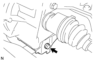
Install the engine with transaxle assembly to the crossmember sub-assembly and the engine mounting member with the bolt.
- Torque:
- 120 N*m { 1,224 kgf*cm, 89 ft.*lbf }
-
Set the engine lifter.
-
Remove the chain block from the engine assembly with transaxle.
-
-
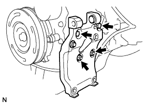
REMOVE ENGINE MOUNT BRACKET
-
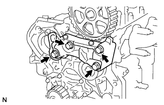
Remove the 4 bolts and engine mount bracket.
-
-
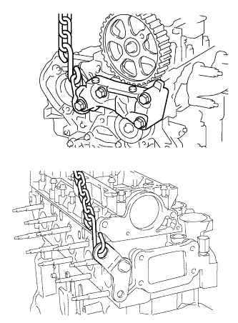
SET TIMING MARK
-
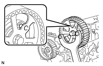
Using SST, set the pulley of the camshaft so that the timing holes of the camshaft drive pulley and the cylinder head are aligned.
- SST
- 09960-10010 ( 09962-01000, 09963-01000 )
-
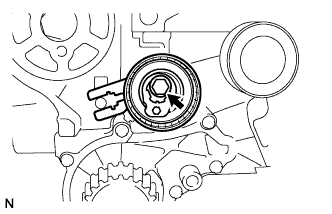
Using the crankshaft pulley bolt, turn the crankshaft so that the timing holes of the crankshaft timing pulley and the oil pump are aligned.
-
-
INSTALL TIMING BELT
-
Temporarily install the timing belt tensioner with the bolt.
-
Install the timing belt.
-
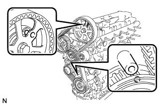
Check that the timing holes are aligned as shown in the illustration.
-
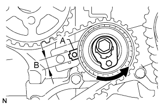
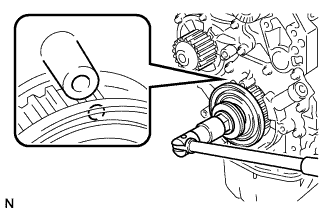
Using a hexagon socket wrench, turn the timing belt tensioner as shown in the illustration.
Tech Tips
Part A should be positioned within area B.
-
Tighten the timing belt tensioner bolt.
- Torque:
- 30 N*m { 306 kgf*cm, 22 ft.*lbf }
-
-
CHECK VALVE TIMING
-
Slowly turn the crankshaft 2 complete revolutions (720°).
-
Check that the timing holes are aligned as shown in the illustration.
-
Remove the crankshaft pulley bolt.
-
-
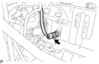
INSTALL CRANK POSITION SENSOR
-
Install the crankshaft timing pulley support with the bolt.
- Torque:
- 5.0 N*m { 51 kgf*cm, 44 in.*lbf }
-
Install the crankshaft position sensor with the bolt.
- Torque:
- 5.0 N*m { 51 kgf*cm, 44 in.*lbf }
-
Connect the crankshaft position sensor connector.
-
-
INSTALL ENGINE MOUNT BRACKET
-
Install the engine mount bracket with the 4 bolts.
- Torque:
- 55 N*m { 561 kgf*cm, 41 ft.*lbf }
-
-
INSTALL TIMING BELT LOWER COVER
-
Install the timing belt lower cover with the 5 bolts.
- Torque:
- 5.0 N*m { 51 kgf*cm, 44 in.*lbf }
-
-
INSTALL CRANKSHAFT PULLEY
-
Temporarily install the timing belt tensioner with the bolt.
-
Using SST, hold the crankshaft pulley.
- SST
- 09330-00021
-
Tighten the bolt.
- Torque:
- 35 N*m { 357 kgf*cm, 26 ft.*lbf }
-
Mark the top surface of the crankshaft pulley bolt with paint.
-
Retighten the bolt by an additional 190 degrees as shown in the illustration.
-
-
INSTALL ALTERNATOR BRACKET NO.2 (w/ Air Conditioning System)
-
Install the alternator bracket No.2 with the 2 bolts and 2 nuts.
- Torque:
- 20 N*m { 204 kgf*cm, 15 ft.*lbf }
-
-
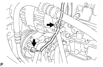
INSTALL GENERATOR ASSEMBLY (w/ Air Conditioning System)
-
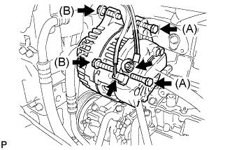
Install the generator assembly with the 4 bolts.
- Torque:
- Bolt A
- 49 N*m { 500 kgf*cm, 36 ft.*lbf }
- Bolt B
- 44 N*m { 449 kgf*cm, 32 ft.*lbf }
-
Install the generator wire to terminal B with the nut.
- Torque:
- 16 N*m { 163 kgf*cm, 12 ft.*lbf }
-
Install the terminal cap.
-
Connect the generator connector.
-
-
INSTALL GENERATOR ASSEMBLY (w/o Air Conditioning System)
-
Install the generator bracket No.2 with the 2 bolts to the generator assembly.
- Torque:
- 20 N*m { 204 kgf*cm, 15 ft.*lbf }
-
Using a hexagon socket wrench, install the V-ribbed belt idler assembly No.1 with the bolt to the generator bracket No.2.
- Torque:
- 48 N*m { 490 kgf*cm, 35 ft.*lbf }
-
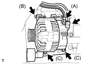
Install the generator assembly with generator bracket No.2 with the 4 bolts.
- Torque:
- Bolt A
- 49 N*m { 500 kgf*cm, 36 ft.*lbf }
- Bolt B
- 44 N*m { 449 kgf*cm, 32 ft.*lbf }
- Bolt C
- 20 N*m { 204 kgf*cm, 15 ft.*lbf }
-
Install the generator wire to terminal B with the nut.
- Torque:
- 16 N*m { 163 kgf*cm, 12 ft.*lbf }
-
Install the terminal cap.
-
Connect the generator connector.
-
-
INSTALL V-RIBBED BELT TENSIONER SUB-ASSEMBLY
-
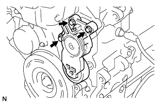
Install the V-ribbed belt tensioner sub-assembly with the 3 bolts.
- Torque:
- 20 N*m { 204 kgf*cm, 15 ft.*lbf }
-
-
CONNECT WIRE HARNESS
-
w/ Air Conditioning System:
-
Connect the wire harness to the generator assembly.
-
Connect the compressor connector.
-
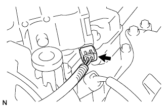
-
Connect the engine oil pressure switch connector.
-
-
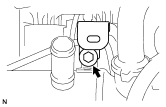
INSTALL STUD BOLT
-
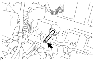
Using a "trox" socket wrench (E7), install the stud bolt.
- Torque:
- 8.0 N*m { 82 kgf*cm, 71 in.*lbf }
-
-
INSTALL OIL LEVEL GAUGE GUIDE
-
Install 2 new O-rings to the oil level gauge guide.
-
Install the oil level gauge guide with the bolt.
- Torque:
- 8.0 N*m { 82 kgf*cm, 71 in.*lbf }
-
-
INSTALL OIL LEVEL GAUGE SUB-ASSEMBLY
-
Install the oil level gauge.
-
-
INSTALL EXHAUST MANIFOLD CONVERTER SUB-ASSEMBLY
-
Temporarily install the exhaust manifold converter clamp, converter separator insulator No.1, catalytic converter support bracket, exhaust manifold converter sub-assembly and 2 nuts.
-
Tighten the 2 nuts to the cylinder block.
- Torque:
- 4.0 N*m { 41 kgf*cm, 35 in.*lbf }
-
Retighten the 2 nuts to the cylinder block.
- Torque:
- 20 N*m { 204 kgf*cm, 15 ft.*lbf }
-
Tighten the nut of the exhaust manifold converter clamp.
- Torque:
- 25 N*m { 255 kgf*cm, 18 ft.*lbf }
-
-
INSTALL MANIFOLD HEAT SHIELD
-
Install the manifold heat shield with the 2 bolts.
- Torque:
- 4.0 N*m { 41 kgf*cm, 35 in.*lbf }
-
-
INSTALL TURBO INSULATOR NO.1
-
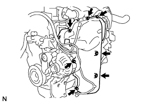
Install the turbo insulator No.1 with the 7 bolts.
- Torque:
- 4.0 N*m { 41 kgf*cm, 35 in.*lbf }
-
-
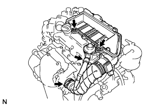
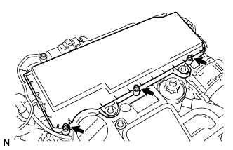
INSTALL CYLINDER HEAD COVER SUB-ASSEMBLY
-
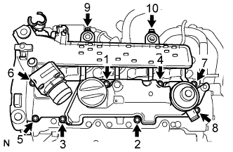
Install 4 new O-rings and a gasket to the cylinder head cover.
-
Temporarily install the cylinder head cover with the 10 bolts.
-
Tighten the 10 bolts in the order shown in the illustration.
- Torque:
- 10 N*m { 102 kgf*cm, 7 ft.*lbf }
-
Connect the diesel throttle valve connector.
-
-
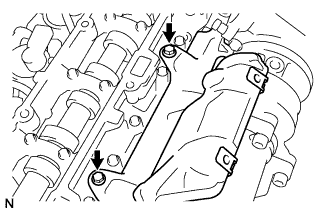
INSTALL EGR VALVE ASSEMBLY
-
Install a new O-ring to the EGR pipe.
-
Temporarily install the EGR valve assembly and gasket with the 2 screws and 2 bolts.
-
Install the clamp with the bolt.
- Torque:
- 6.0 N*m { 61 kgf*cm, 53 in.*lbf }
-
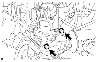
Tighten the 2 bolts.
- Torque:
- 10 N*m { 102 kgf*cm, 7 ft.*lbf }
-
Using a "torx" socket wrench, tighten the 2 screws.
- Torque:
- 5.0 N*m { 51 kgf*cm, 44 in.*lbf }
-
-
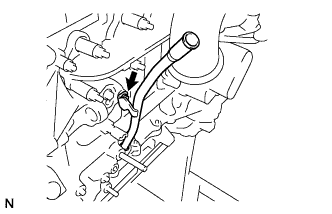
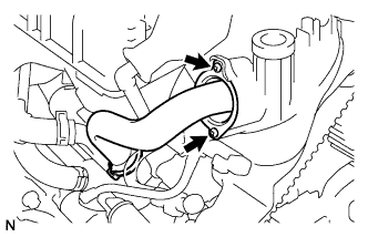
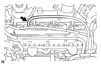
INSTALL EGR COOLER WATER BY-PASS HOSE
-
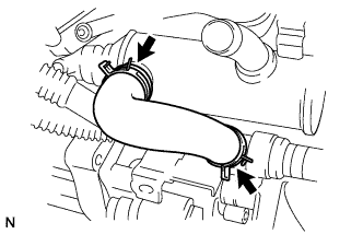
Using pliers, slide the 2 clips to install the water by-pass hose.
-
-
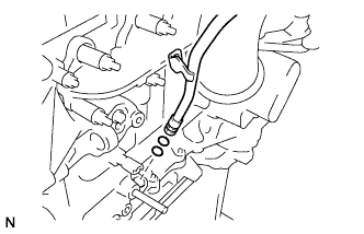
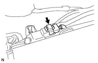
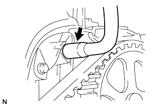
INSTALL HEATER WATER OUTLET HOSE A
-
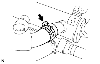
Using pliers, slide the clip to install the heater water outlet hose A.
-
-
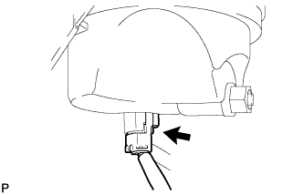
INSTALL ENGINE WIRE NO.2
-
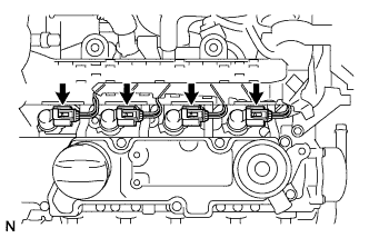
Install the engine wire No.2 to the injector.
CAUTION:
Be sure to connect the injector connectors correctly to prevent malfunctions in the injector.
-
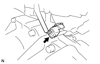
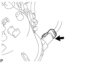
Connect the fuel pressure sensor connector.
-
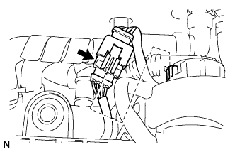
Connect the glow harness connector.
-
-
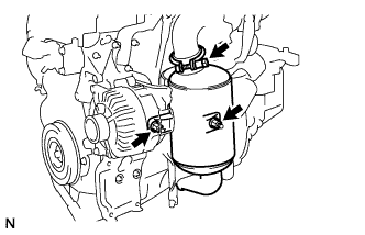
INSTALL FUEL FILTER ASSEMBLY
-
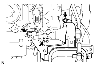
Temporarily install the fuel filter assembly with the 2 bolts and screw.
-
Tighten the 2 bolts.
- Torque:
- 10 N*m { 102 kgf*cm, 7 ft.*lbf }
-
Using a "torx" socket wrench, tighten the screw.
- Torque:
- 5.0 N*m { 51 kgf*cm, 44 in.*lbf }
-
Connect the fuel heater connector.
-
Connect the fuel level warning switch connector.
-
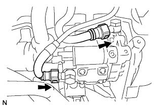
Align the connector with the pipe, then push in the connector to the pipe until it makes a "click" sound to connect the fuel return hose to the fuel pump return pipe.
-
Align the connector with the pipe, then push in the connector to the pipe until it makes a "click" sound to connect the fuel hose to the fuel pump pipe.
-
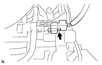
Connect the pressure control valve connector.
-
Connect the fuel return hose to the No.4 injector.
-
-
INSTALL AIR CLEANER CASE SUB-ASSEMBLY
-
Temporarily install the air cleaner case, air hose No.1 clamp and 2 screws.
-
Using a "torx" socket wrench, tighten the 2 screws.
- Torque:
- 5.0 N*m { 51 kgf*cm, 44 in.*lbf }
-
Tighten the air hose No.1 clamp.
- Torque:
- 5.0 N*m { 51 kgf*cm, 44 in.*lbf }
-
Connect the PCV hose.
-
-
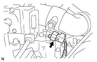
INSTALL TURBO PRESSURE SENSOR
-
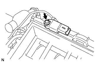
Install the turbo pressure sensor with the bolt.
- Torque:
- 4.0 N*m { 41 kgf*cm, 35 in.*lbf }
-
Connect the turbo pressure sensor connector.
-
Connect the turbo pressure sensor to the cylinder head cover.
-
-
INSTALL INTAKE AIR RESONATOR
-
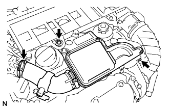
Install a new O-ring to the intake air resonator.
-
Temporarily install the intake air resonator with the clamp, bolt and screw.
-
Tighten the bolt.
- Torque:
- 7.5 N*m { 77 kgf*cm, 66 in.*lbf }
-
Tighten the air hose No.1 clamp.
- Torque:
- 3.5 N*m { 36 kgf*cm, 31 in.*lbf }
-
Using a "torx" socket wrench, tighten the screw.
- Torque:
- 7.5 N*m { 77 kgf*cm, 66 in.*lbf }
-
Connect the air temperature sensor connector.
-
-
INSTALL AIR CLEANER CAP SUB-ASSEMBLY
-
Install the air filter element.
-
Using a "torx" socket wrench, install the air cleaner case sub-assembly with the 3 screws.
- Torque:
- 5.0 N*m { 51 kgf*cm, 44 in.*lbf }
-
-
INSTALL TIMING BELT UPPER COVER
-
Install the timing belt upper cover with the 5 bolts.
- Torque:
- 5.0 N*m { 51 kgf*cm, 44 in.*lbf }
-
-
INSTALL ENGINE W/ TRANSAXLE