OIL PUMP REMOVAL

-
REMOVE ENGINE W/ TRANSAXLE
-
REMOVE TIMING BELT UPPER COVER
-
Remove the 5 bolts and timing belt upper cover.
-
-
REMOVE AIR CLEANER CAP SUB-ASSEMBLY
-
Using a "torx" socket wrench, remove the 3 screws.
-
Remove the air cleaner cap sub-assembly.
-
Remove the air filter element.
-
-
REMOVE INTAKE AIR RESONATOR
-
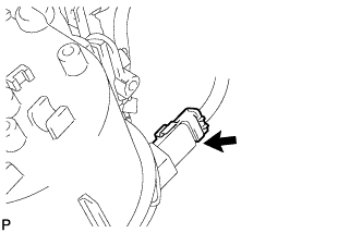
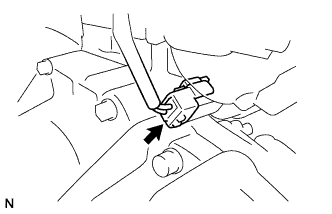
Disconnect the intake air temperature sensor connector.
-
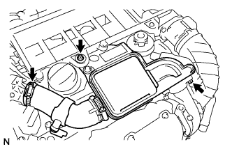
Loosen the air hose No.2 clamp.
-
Using a "torx" socket wrench, remove the screw.
-
Remove the bolt, intake air resonator and O-ring.
-
-
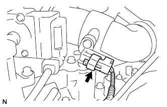
REMOVE TURBO PRESSURE SENSOR
-
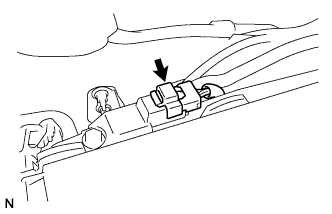
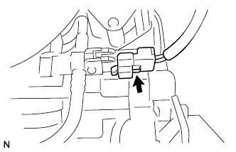
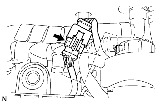
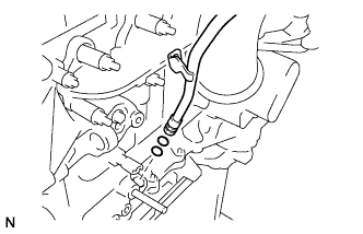
Disconnect the turbo pressure sensor connector.
-
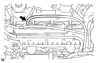
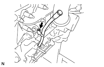
Disconnect the turbo pressure sensor hose from the cylinder head cover.
-
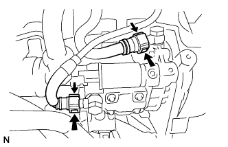
Remove the bolt and turbo pressure sensor.
-
-
REMOVE AIR CLEANER CASE SUB-ASSEMBLY
-
Loosen the air hose No.1 clamp.
-
Disconnect the PCV hose from the cylinder head cover.
-
Using a "torx" socket wrench, remove the 2 screws.
-
Remove the air cleaner case sub-assembly.
-
-
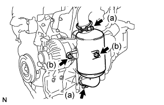
REMOVE FUEL FILTER ASSEMBLY
-
Disconnect the fuel return hose from the No.4 injector.
-
Disconnect the fuel temperature sensor connector.
-
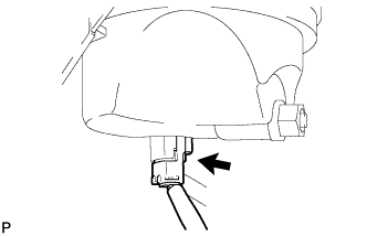
Pinch the retainer as illustrated, then pull out the fuel hose from the fuel pump.
-
Pinch the retainer as illustrated, then pull out the fuel return hose from the fuel pump.
-
Disconnect the fuel level warning switch connector.
-
Disconnect the fuel heater hose connector (w/ fuel heater).
-
Using a "torx" socket wrench, remove the screw.
-
Remove the 2 bolts, fuel filter, and fuel bracket with priming pump.
-
-
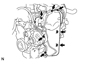
DISCONNECT ENGINE WIRE NO.2
-
Disconnect the glow harness connector.
-
Disconnect the fuel pressure sensor connector.
-
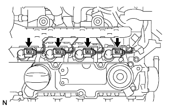
Disconnect the 4 injector connectors and remove the engine wire No.2.
-
-
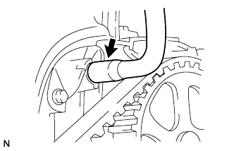
REMOVE HEATER WATER OUTLET HOSE A
-
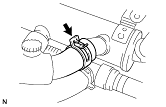
Using pliers, slide the clip to remove the heater water outlet hose A.
-
-
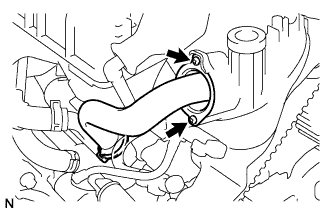
REMOVE EGR COOLER WATER BY-PASS HOSE
-
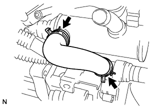
Using pliers, grip the claws of the 2 clips and slide the 2 clips to remove the water by-pass hose.
-
-
REMOVE EGR VALVE ASSEMBLY
-
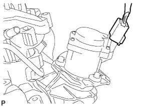
Disconnect the EGR valve connector.
-
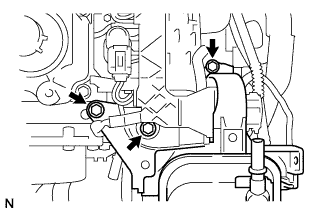
Using a "torx" socket wrench, remove the 2 screws.
-
Remove the bolt and clamp from the EGR pipe.
-
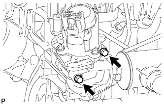
Remove the 2 bolts from the EGR valve.
-
Remove the EGR valve assembly, gasket and O-ring.
-
-
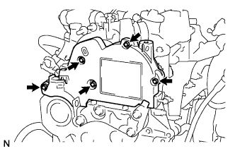
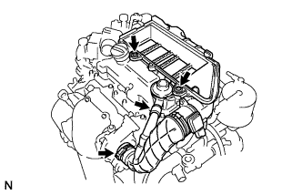
REMOVE CYLINDER HEAD COVER SUB-ASSEMBLY
-
Disconnect the diesel throttle valve connector.
-
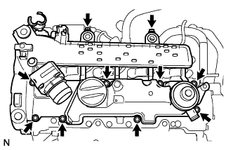
Remove the 10 bolts, cylinder head cover sub-assembly, gasket and 4 O-rings.
-
-
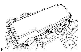
REMOVE TURBO INSULATOR NO.1
-
Remove the 7 bolts and turbo insulator No.1.
-
-
REMOVE MANIFOLD HEAT SHIELD
-
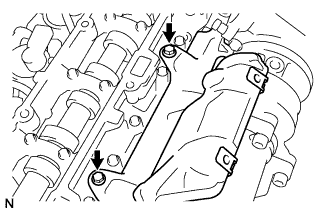
Remove the 2 bolts and manifold heat shield.
-
-
REMOVE EXHAUST MANIFOLD CONVERTER SUB-ASSEMBLY
-
Remove the 2 nuts and 2 exhaust manifold converter clamps.
-
Remove the 2 nuts, exhaust manifold converter sub-assembly, catalytic converter support bracket, and converter separator insulator No.1.
-
-
REMOVE OIL LEVEL GAUGE SUB-ASSEMBLY
-
REMOVE OIL LEVEL GAUGE GUIDE
-
Remove the bolt and oil level gauge guide.
-
Remove the 2 O-rings from the oil level gauge guide.
-
-
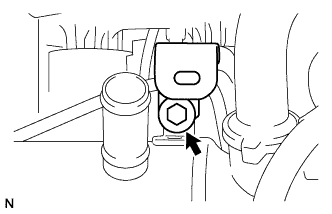
REMOVE STUD BOLT
-
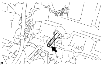
Using a "trox" socket wrench (E7), remove the stud bolt.
-
-
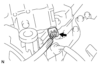
DISCONNECT WIRE HARNESS
-
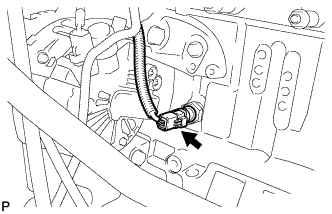
Disconnect the engine oil pressure switch connector.
-
w/ Air Conditioning System:
-
Disconnect the wire harness from the generator assembly.
-
Disconnect the compressor connector.
-
-
-
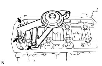
REMOVE V-RIBBED BELT TENSIONER SUB-ASSEMBLY
-
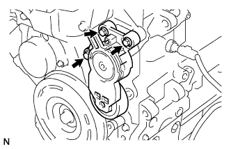
Remove the 3 bolts and V-ribbed belt tensioner sub-assembly.
-
-
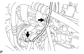
REMOVE GENERATOR ASSEMBLY (w/ Air Conditioning System)
-
Disconnect the generator connector.
-
Remove the terminal cap.
-
Remove the nut and disconnect the wire harness from terminal B.
-
Remove the 4 bolts and generator assembly.
-
-
REMOVE ALTERNATOR BRACKET NO.2 (w/ Air Conditioning System)
-
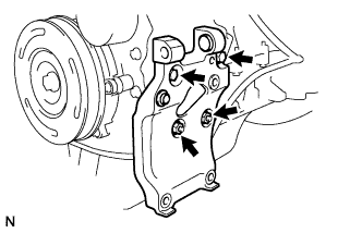
Remove the 2 nuts, 2 bolts and alternator bracket No.2.
-
-
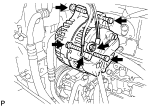
REMOVE GENERATOR ASSEMBLY (w/o Air Conditioning System)
-
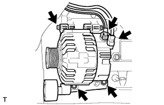
Disconnect the generator connector.
-
Remove the terminal cap.
-
Remove the nut and disconnect the wire harness from terminal B.
-
Remove the 4 bolts and generator assembly with generator bracket No.2.
-
Using a hexagon socket wrench, remove the bolt and V-ribbed belt idler assembly No.1 from the generator bracket No.2.
-
Remove the 2 bolts and generator bracket No.2 from the generator assembly.
-
-
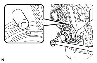
REMOVE CRANKSHAFT PULLEY
-
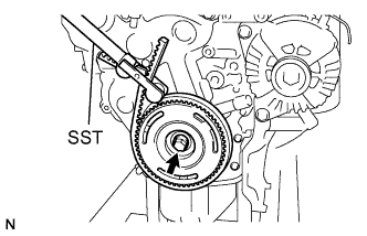
Using SST, hold the crankshaft pulley.
- SST
- 09330-00021
-
Remove the bolt and crankshaft pulley.
-
-
REMOVE TIMING BELT LOWER COVER
-
Remove the 5 bolts and timing belt lower cover.
-
-
REMOVE ENGINE MOUNT BRACKET
-
Remove the 4 bolts and engine mount bracket.
-
-
SET TIMING MARK
-
Using the crankshaft pulley bolt, turn the crankshaft so that the timing holes of the crankshaft timing pulley and the oil pump are aligned.
-
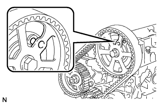
Check that the timing holes of the camshaft drive pulley and the cylinder head are aligned.
-
-
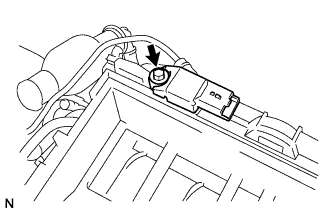
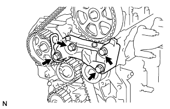
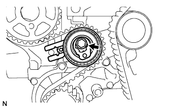
REMOVE CRANK POSITION SENSOR
-
Disconnect the crank position sensor connector.
-
Remove the bolt and crank position sensor.
-
Remove the bolt and crankshaft timing pulley support.
-
-
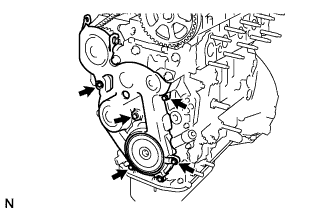
REMOVE TIMING BELT
-
Remove the bolt and timing belt tensioner.
-
Remove the timing belt.
-
-
INSTALL ENGINE MOUNT BRACKET
-
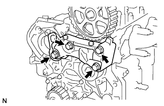
Install the engine mount bracket with the 4 bolts.
- Torque:
- 55 N*m { 561 kgf*cm, 41 ft.*lbf }
-
-
SEPARATE FRONT SUSPENSION CROSSMEMBER SUB-ASSEMBLY
-
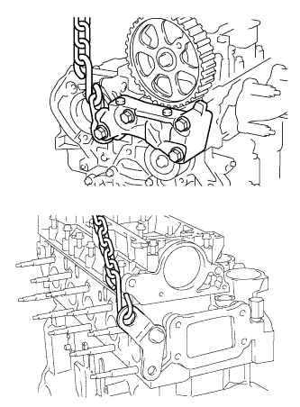
Attach the engine sling and hang the engine with the chain block.
-
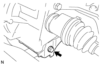
Remove the bolt, then separate the engine with transaxle assembly from the front suspension crossmember assembly.
-
-
REMOVE STARTER ASSEMBLY
-
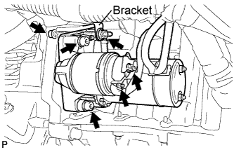
Remove the bolt and remove the wire harness clamp bracket.
-
Remove the nut and disconnect the wire harness from terminal 30.
-
Remove the nut and disconnect the wire harness from terminal 50.
-
Using a hexagon wrench (6 mm), remove the 3 bolts and remove the starter.
-
-
REMOVE MANUAL TRANSAXLE ASSEMBLY
-
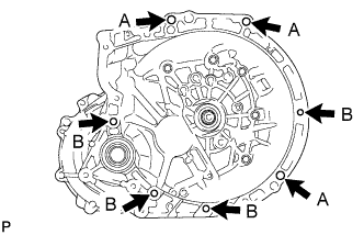
Remove the 7 bolts and manual transaxle from the engine.
Tech Tips
-
Remove 3 A bolts from the transaxle side.
-
Remove 4 B bolts from the engine side.
-
-
-
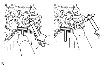
INSTALL CRANKSHAFT PULLEY
-
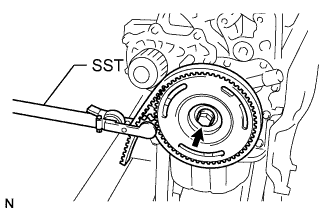
Install the crankshaft pulley with the bolt.
-
Using SST, hold the crankshaft pulley.
- SST
- 09330-00021
-
Tighten the bolt.
- Torque:
- 35 N*m { 357 kgf*cm, 26 ft.*lbf }
-
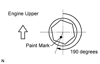
Mark the top surface of the crankshaft pulley bolt with paint.
-
Retighten the bolt by additional 190 degrees as shown in the illustration.
-
-
REMOVE FLYWHEEL SUB-ASSEMBLY
-
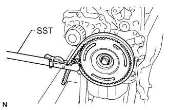
Using SST, hold the crankshaft pulley.
- SST
- 09330-00021
-
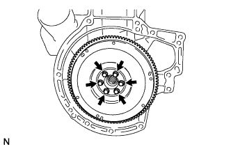
Remove the 6 bolts and flywheel sub-assembly.
-
-
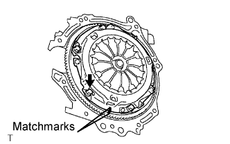
REMOVE CLUTCH COVER ASSEMBLY
-
Align the matchmark on the clutch cover with the one on the flywheel.
-
Loosen each set bolt by one turn at a time until the spring tension is released.
-
Remove the set bolts and the clutch cover.
Note
Do not drop the clutch disc.
-
-
REMOVE CLUTCH DISC ASSEMBLY
Note
Do not allow any oil or foreign matter to adhere to the lining part of the clutch disk or the surfaces of the pressure plate and flywheel.
-
REMOVE OIL PAN SUB-ASSEMBLY
-
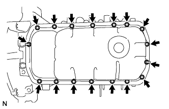
Remove the 2 nuts and 15 bolts.
-
Using an oil pan cutter, remove the oil pan sub-assembly from the cylinder block assembly.
- SST
- 09032-00100
-
-
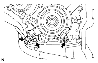
REMOVE OIL STRAINER SUB-ASSEMBLY
-
Using a hexagon socket wrench, remove the 3 bolts, oil strainer sub-assembly and gaskets.
-
-
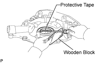
REMOVE OIL PUMP ASSEMBLY
-
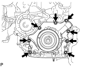
Remove the 8 bolts.
-
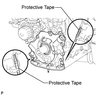
Remove the oil pump assembly by prying between the oil pump assembly and cylinder block with a screwdriver.
Note
Be careful not to damage the contact surfaces of the cylinder block and oil pump assembly.
Tech Tips
Tape the screwdriver tip before use.
-
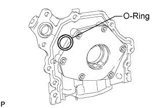
Remove the O-ring from the oil pump assembly.
-
-
REMOVE CRANK OIL SEAL
-
Using a screwdriver with its tip taped, pry out the crank oil seal.
Tech Tips
Tape the screwdriver tip before use.
-