OIL PUMP INSTALLATION

-
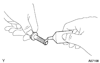
INSTALL TIMING CHAIN OR BELT COVER OIL SEAL
-
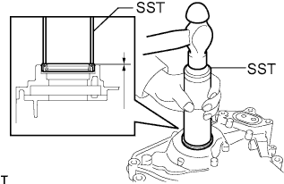
Using SST, tap in a new oil seal until its surface is flush with the timing gear case edge.
- SST
- 09608-06041
Standard distance 0.5 to -1 mm (0.0197 to -0.0394 in.) Note
-
Keep the lip free from foreign matter.
-
Do not tap the oil seal at an angle.
-
-
INSTALL OIL PUMP GASKET
-
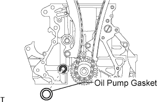
Install a new oil pump gasket.
-
-
INSTALL TIMING CHAIN OR BELT COVER SUB-ASSEMBLY
-
Apply seal packing in a continuous bead to the engine unit as shown in the following illustration.
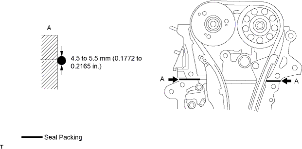
Seal packing Part No.08826-00080 or equivalent Seal width 4.5 to 5.5 mm (0.1772 to 0.2165 in.) Note
-
When the contact surfaces are wet, wipe off with an oil-free cloth before applying seal packing.
-
Install the crankcase within 3 minutes and tighten the bolts within 15 minutes after applying seal packing.
-
Do not start the engine for at least 2 hours after installing.
-
-
Apply seal packing in a continuous bead to the timing chain cover as shown in the following illustration.
Seal packing Part No.08826-00080 or equivalent Seal packing Part No.08826-00100 or equivalent Note
-
When the contact surfaces are wet, wipe off with an oil-free cloth before applying seal packing.
-
Install the crankcase within 3 minutes and tighten the bolts within 15 minutes after applying seal packing.
-
Do not start the engine for at least 2 hours after installing.
Tech Tips
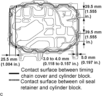
Apply seal packing referring to the table and illustration below.
Seal packing diameter Continuous line area 3.0 mm (0.1181 in.) Alternate long and short dashed line area 3.5 to 4.5 mm (0.1378 to 0.1772 in.) Dashed line area 3.0 to 3.5 mm (0.1181 to 0.1378 in.) 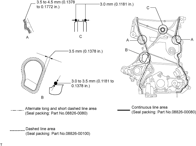
-
-
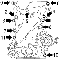
Using several steps, uniformly install and tighten the 11 bolts in the sequence shown in the illustration.
- Torque:
- Bolts 9, 10, and 11
- 24 N*m { 245 kgf*cm, 18 ft.*lbf }
- Bolts except 9, 10, and 11
- 40 N*m { 408 kgf*cm, 30 ft.*lbf }
-
-
INSTALL OIL PAN SUB-ASSEMBLY
-
Remove any grease from the installation surfaces of the cylinder block sub-assembly and oil pan sub-assembly.
-
Apply seal packing to the oil pan sub-assembly and install it to the cylinder block assembly.
Seal packing Part No. 08826-00080 or equivalent. Note
-
The start and end points of seal packing application must be on the seal surface with the cylinder block sub-assembly.
-
Be sure to apply seal packing to the contact surfaces between the timing chain cover and cylinder block, and between the oil seal retainer and cylinder block.
-
Install the oil pan sub-assembly within 3 minutes and tighten the bolts within 15 minutes after applying seal packing.
-
-
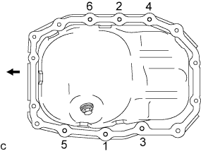
Tighten the specified 6 bolts in the order shown in the illustration.
- Torque:
- 24 N*m { 245 kgf*cm, 18 ft.*lbf }
-
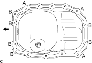
The remaining 7 bolts and 2 nuts can be tightened in optional order.
- Torque:
- 24 N*m { 245 kgf*cm, 18 ft.*lbf, for A }
- 10 N*m { 102 kgf*cm, 7 ft.*lbf, for B }
-
-
INSTALL WATER PUMP ASSEMBLY
-
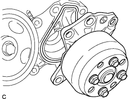
Install a new water pump gasket to the timing chain cover assembly and then install the water pump assembly.
-
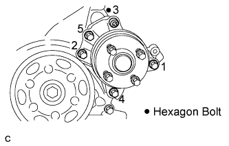
Tighten the 5 bolts in the order shown in the illustration.
- SST
- 09043-88010
- Torque:
- 28 N*m { 286 kgf*cm, 21 ft.*lbf }
-
-
INSTALL OIL FILTER BRACKET
-
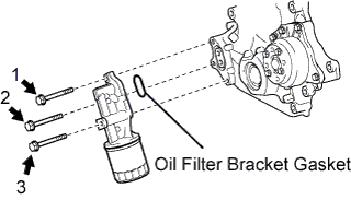
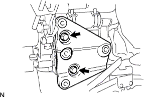
Using several steps, uniformly install and tighten the 3 bolts in the sequence shown in the illustration.
- Torque:
- 24 N*m { 245 kgf*cm, 18 ft.*lbf }
-
-
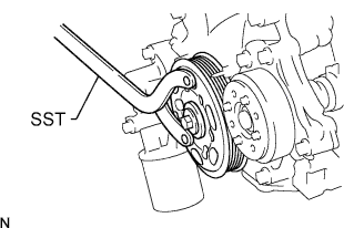
INSTALL CRANKSHAFT PULLEY
-
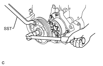
Hold the crankshaft pulley with SST and tighten the bolt.
- SST
- 09960-10010 ( 09962-01000, 09963-01000 )
- Torque:
- 170 N*m { 1,734 kgf*cm, 125 ft.*lbf }
-
-
INSTALL CRANK POSITION SENSOR
Note
-
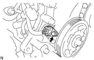
Do not use parts that have been dropped or received strong impact.
-
Make sure that the O-ring is not damaged before installing it.
-
Apply a light coat of engine oil to the O-ring.
-
Install the crankshaft position sensor with the bolt.
- Torque:
- 7.5 N*m { 77 kgf*cm, 66 in.*lbf }
-
Connect the crankshaft position sensor connector.
-
-
INSTALL CYLINDER HEAD COVER SUB-ASSEMBLY
-
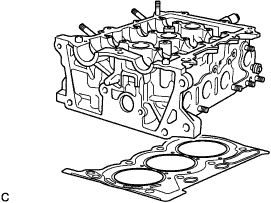
Place a new cylinder head gasket on the cylinder block sub-assembly.
Note
Place the cylinder head gently in order not to damage the gasket.
-
Place the cylinder head on the cylinder block sub-assembly.
-
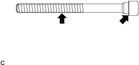
Apply engine oil to each bolt thread and seating surface and install them.
-
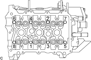
Tighten the bolts in 2 or 3 steps in the order shown in the illustration to install the cylinder head sub-assembly.
-
Tighten the bolts to the specified torque.
- Torque:
- 32 N*m { 326 kgf*cm, 24 ft.*lbf }
-
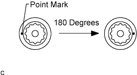
Mark the front of each cylinder head bolt with paint.
-
Retighten the bolts by 180 degrees in the order indicated in step (d).
-
Check that the painted marks are now at 180 degrees opposite to the front.
-
-
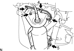
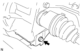
INSTALL WATER BY-PASS PIPE NO.1
-
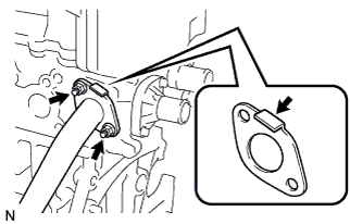
Install a new water by-pass pipe gasket and water by-pass pipe No.1 with the 2 nuts.
- Torque:
- 24 N*m { 245 kgf*cm, 18 ft.*lbf }
Note
Be sure to install the gasket in the direction shown in the illustration.
-
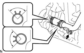
Install the water by-pass hose to the water by-pass pipe with the clip.
Note
-
Be sure to install the clip as shown in the illustration.
-
Be sure to insert the water by-pass hose to the stay edge of the water by-pass pipe.
-
-
Install the water by-pass pipe with the bolt.
- Torque:
- 24 N*m { 245 kgf*cm, 18 ft.*lbf }
-
-
INSTALL COMPRESSOR MOUNTING BRACKET NO.1
-
Install the compressor mounting bracket with the 2 bolts.
- Torque:
- 24.5 N*m { 250 kgf*cm, 18 ft.*lbf }
-
-
INSTALL EXHAUST MANIFOLD
-
Install the exhaust manifold gasket.
-
Install the exhaust manifold with the 3 bolts and 2 nuts.
- Torque:
- 24 N*m { 245 kgf*cm, 18 ft.*lbf }
Note
Tighten the bolts and nuts in the order shown in the illustration.
-
-
INSTALL FAN BELT ADJUSTING BAR
-
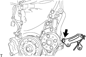
Instal the fan belt adjusting bar with the bolt.
- Torque:
- 34 N*m { 347 kgf*cm, 25 ft.*lbf }
-
-
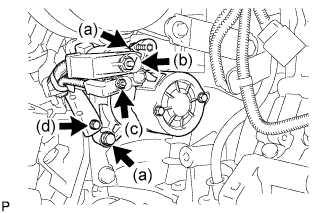
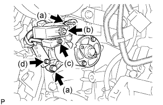
INSTALL GENERATOR ASSEMBLY
-
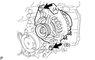
Install the generator with the 2 bolts.
- Torque:
- Bolt (A)
- 54 N*m { 551 kgf*cm, 40 ft.*lbf }
- Bolt (B)
- 34 N*m { 347 kgf*cm, 25 ft.*lbf }
-
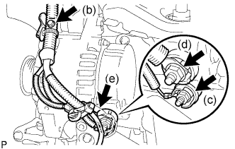
Install the wire harness clamp with the bolt.
- Torque:
- 8.4 N*m { 85 kgf*cm, 74 in.*lbf }
-
Install the generator wire with the nut to the terminal D.
- Torque:
- 4.5 N*m { 46 kgf*cm, 40 in.*lbf }
-
Install the generator wire with the nut to the terminal B.
- Torque:
- 9.0 N*m { 92 kgf*cm, 80 in.*lbf }
-
Install the terminal cap.
-
-
INSTALL IGNITION COIL NO.1
-
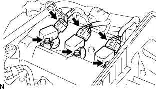
Install the 3 ignition coils with the 3 bolts.
- Torque:
- 8.9 N*m { 91 kgf*cm, 79 in.*lbf }
-
Connect the 3 connectors.
-
-
INSTALL FLYWHEEL SUB-ASSEMBLY
-
Using SST, hold the crankshaft.
- SST
- 09960-10010 ( 09962-01000, 09963-01000 )
-
Clean the bolts and their holes.
-
Apply adhesive to the 2 or 3 threads of the bolt end.
Adhesive Part No. 08833-00070, THREE BOND 1324 or equivalent -
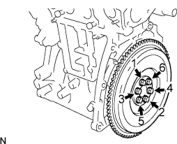
Install the flywheel sub-assembly with the 6 bolts.
- Torque:
- 78 N*m { 796 kgf*cm, 58 ft.*lbf }
Note
Tighten the bolts in the order shown in the illustration.
-
-
INSTALL CLUTCH DISC ASSEMBLY
- SST
- 09301-00210
-
Install the clutch disc assembly Click here.
-
INSTALL CLUTCH COVER ASSEMBLY
- SST
- 09301-00210
-
Install the clutch cover assembly Click here.
-
INSTALL MANUAL TRANSAXLE ASSEMBLY
-
Install the manual transaxle assembly Click here.
-
-
INSTALL STARTER ASSEMBLY (for Standard)
-
Install the starter with the 2 bolts.
- Torque:
- 37 N*m { 380 kgf*cm, 27 ft.*lbf }
-
Connect the wire harness to terminal 30 and install the nut.
- Torque:
- 9.5 N*m { 97 kgf*cm, 84 in.*lbf }
-
Connect the wire harness to terminal 50 and install the nut.
- Torque:
- 5.0 N*m { 51 kgf*cm, 44 in.*lbf }
-
Install the wire harness clamp with the bolt.
- Torque:
- 8.4 N*m { 85 kgf*cm, 74 in.*lbf }
-
-
REMOVE STARTER ASSEMBLY (for Cold Area)
-
Install the starter with the 2 bolts.
- Torque:
- 37 N*m { 380 kgf*cm, 27 ft.*lbf }
-
Connect the wire harness to terminal 30 and install the nut.
- Torque:
- 9.5 N*m { 97 kgf*cm, 84 in.*lbf }
-
Connect the wire harness to terminal 50 and install the nut.
- Torque:
- 5.0 N*m { 51 kgf*cm, 44 in.*lbf }
-
Install the wire harness clamp with the bolt.
- Torque:
- 8.4 N*m { 85 kgf*cm, 74 in.*lbf }
-
-
INSTALL FRONT SUSPENSION CROSSMEMBER SUB-ASSEMBLY
-
Install the engine and transaxle assembly to the crossmember sub-assembly and the engine mounting member with the bolt.
- Torque:
- 120 N*m { 1,224 kgf*cm, 89 ft.*lbf }
-
-
INSTALL ENGINE ASSEMBLY W/ TRANSAXLE