OIL PUMP REMOVAL

-
REMOVE ENGINE ASSEMBLY W/ TRANSAXLE
-
SEPARATE FRONT SUSPENSION CROSSMEMBER SUB-ASSEMBLY
-
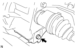
Remove the bolt and the engine assembly with transaxle from the front suspension crossmember assembly.
-
-
REMOVE STARTER ASSEMBLY (for Standard)
-
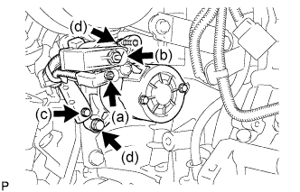
Open the terminal cap, remove the nut and disconnect the wire harness from terminal 50.
-
Open the terminal cap, remove the nut and disconnect the wire harness from terminal 30.
-
Remove the bolt, and wire harness clamp.
-
Remove the 2 bolts, and the starter.
-
-
REMOVE STARTER ASSEMBLY (for Cold Area)
-
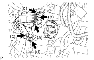
Open the terminal cap, remove the nut and disconnect the wire harness from terminal 50.
-
Open the terminal cap, remove the nut and disconnect the wire harness from terminal 30.
-
Remove the bolt, and wire harness clamp.
-
Remove the 2 bolts, and the starter.
-
-
REMOVE MANUAL TRANSAXLE ASSEMBLY
-
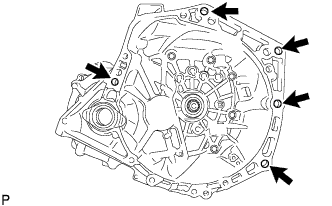
Remove the 5 bolts and the manual transaxle assembly from the engine assembly.
Note
-
To avoid damage to the knock pins, do not pry between the manual transaxle assembly and the engine assembly.
-
To avoid damage to the input shaft, do not forcefully shake the manual transaxle assembly.
-
-
-
REMOVE CLUTCH COVER ASSEMBLY
-
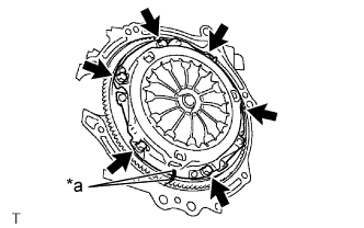
Text in Illustration *a Matchmark Place matchmarks on the clutch cover assembly and the flywheel sub-assembly.
-
Loosen each bolt by one turn at a time until the spring tension is released.
-
Remove the 6 bolts, and pull off the clutch cover assembly with the clutch disc assembly.
Note
-
Do not drop the clutch disc assembly.
-
When replacing the clutch disc assembly, be sure to replace it together with the clutch cover assembly as a set.
-
-
-
REMOVE CLUTCH DISC ASSEMBLY
Note
Do not attach any oil or foreign matter to the lining part of the clutch disc assembly or the surfaces of the pressure plate and flywheel sub-assembly.
-
REMOVE FLYWHEEL SUB-ASSEMBLY
-
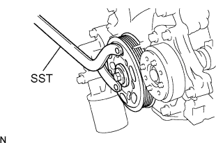
Hold the crankshaft with SST.
- SST
- 09960-10010 ( 09962-01000, 09963-01000 )
-

Remove the 6 bolts and flywheel sub-assembly.
-
-
REMOVE IGNITION COIL NO.1
-
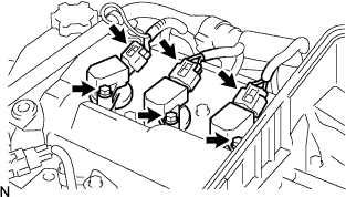
Disconnect the 3 connectors.
-
Remove the 3 bolts and 3 No. 1 ignition coils.
-
-
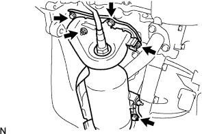
REMOVE GENERATOR ASSEMBLY
-
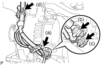
Remove the terminal cap.
-
Remove the nut and disconnect the wire harness from terminal B.
-
Remove the nut and disconnect the wire harness from terminal D.
-
Remove the bolt and disconnect the wire harness clamp from generator.
-
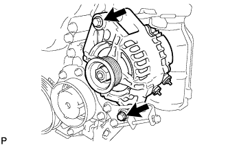
Remove the 2 bolts and generator.
-
-
REMOVE FAN BELT ADJUSTING BAR
-
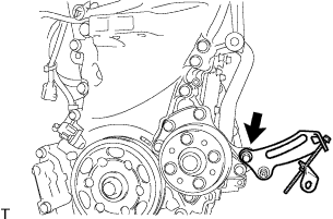
Remove the bolt and fan belt adjusting bar from the timing chain or belt cover.
-
-
REMOVE EXHAUST MANIFOLD
-
Remove the 3 bolts, 2 nuts, and exhaust manifold.
-
Remove the exhaust manifold gasket.
-
-
REMOVE COMPRESSOR MOUNTING BRACKET NO.1
-
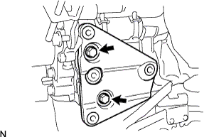
Remove the 2 bolts and No. 1 compressor mounting bracket.
-
-
REMOVE WATER BY-PASS PIPE NO.1
-
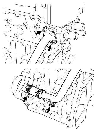
Remove the bolt and 2 nuts.
-
Loosen the hose clip and remove the No. 1 water by-pass pipe with water by-pass hose.
-
Remove the water by-pass pipe gasket.
-
-
REMOVE CYLINDER HEAD COVER SUB-ASSEMBLY
-

Remove the 13 bolts and 2 nuts in the order shown in the illustration.
-
Remove the cylinder head cover gasket from the cylinder head cover.
-
-
REMOVE CRANK POSITION SENSOR
-
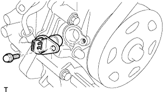
Disconnect the sensor connector.
-
Remove the bolt and sensor.
-
-
REMOVE CRANKSHAFT PULLEY
-
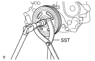
Using SST, hold the crankshaft pulley and loosen the pulley bolt.
- SST
- 09960-10010 ( 09962-01000, 09963-01000 )
-
Remove the crankshaft pulley.
-
-
REMOVE OIL FILTER BRACKET
-
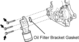
Remove the 3 bolts, oil filter bracket and oil filter bracket gasket.
-
-
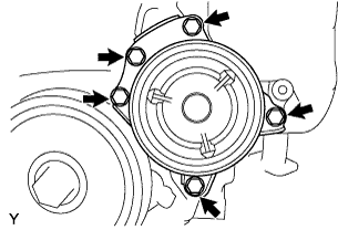
REMOVE ENGINE WATER PUMP ASSEMBLY
-
Remove the 5 bolts and the engine water pump.
-
Remove the water pump gasket.
-
-
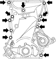
REMOVE OIL PAN SUB-ASSEMBLY
-
Remove the 13 bolts and 2 nuts.
-
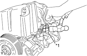
Text in Illustration *1 Oil Pan Seal Cutter Using an oil pan seal cutter, remove the oil pan.
Note
Do not damage the flange of the oil pan.
-
-
REMOVE TIMING CHAIN OR BELT COVER SUB-ASSEMBLY
-
Remove the 11 bolts.
-
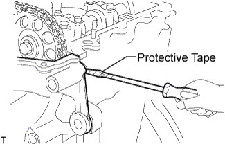
Remove the timing chain or belt cover by prying between the timing chain or belt cover and cylinder head or cylinder block with a screwdriver.
Note
Be careful not to damage the contact surfaces of the cylinder head, cylinder block and timing chain cover.
Tech Tips
Tape the screwdriver tip before use.
-
-
REMOVE OIL PUMP GASKET
-
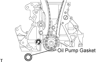
Remove the oil pump gasket.
-
-
REMOVE TIMING CHAIN OR BELT COVER OIL SEAL
-
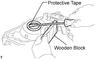
Using a screwdriver with its tip taped, pry out the oil seal.
Tech Tips
Tape the screwdriver tip before use.
-