STARTER (for Cold Area) INSPECTION

-
INSPECT STARTER ARMATURE ASSEMBLY
-
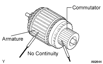
Check the commutator for open circuit.
-
Using an ohmmeter, check that there is continuity between the segments of the commutator.
If there is no continuity between any segments, replace the starter armature.
-
-
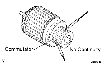
Check the commutator for ground.
-
Using an ohmmeter, check that there is no continuity between the commutator and armature core.
If there is continuity, replace the starter armature.
-
-
Check the commutator for dirt and / or burns on the surface.
If the surface is dirty or burnt, correct it with sandpaper (No.400) or a lathe.
-
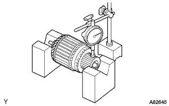
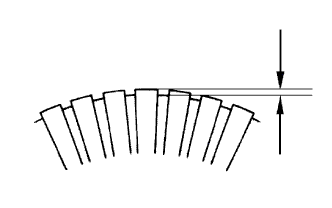
Check for the commutator circuit runout.
-
Place the commutator on V-blocks.
-
Using a dial indicator, measure the circle runout.
Standard runout 0.02 mm (0.0008 in.) Maximum runout 0.04 mm (0.0016 in.) If the runout is greater than maximum, replace the armature.
-
-
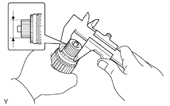
Using vernier calipers, measure the commutator diameter.
Standard diameter 29.9 mm (1.1772 in.) Minimum diameter 28.8 mm (1.1339 in.) If the diameter is less than minimum, replace the armature.
-
Using vernier calipers, measure the undercut depth of the commutator.
Standard depth 0.9 mm (0.0354 in.) Limit depth 0.4 mm (0.0157 in.)
-
-
INSPECT STARTER BRUSH HOLDER ASSEMBLY
-
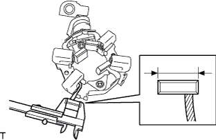
Using vernier calipers, measure the brush length.
Standard length 10.5 mm (0.4134 in.) Minimum length 7.0 mm (0.2756 in.) If the length is less than minimum, replace the starter brush holder.
-
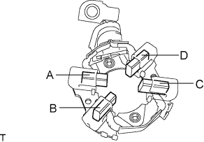
Check the brush holder.
-
Using an ohmmeter, measure the resistance between the brushes.
Standard Tester Connection Specified Condition A-B 10 kΩ or higher A-C 10 kΩ or higher A-D Below 1 Ω B-C Below 1 Ω B-D 10 kΩ or higher C-D 10 kΩ or higher If the standard is not met, replace the starter brush holder.
-
-
-
INSPECT STARTER CLUTCH SUB-ASSEMBLY
-
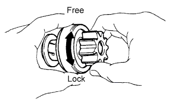
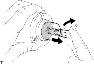
Check the starter clutch pinion gear.
-
Hold the starter clutch and rotate the pinion gear clockwise, and check that it turns freely. Try to rotate the pinion gear counterclockwise and check that it locks.
If necessary, replace the starter center clutch.
-
-
-
INSPECT MAGNET STARTER SWITCH ASSEMBLY
-
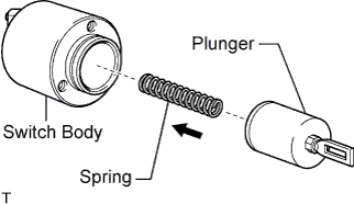
Check the plunger.
-
Install the plunger and spring onto the switch body.
-
-
Push in the plunger and check that it returns quickly to its original position.
If necessary, replace the magnet starter switch.
-
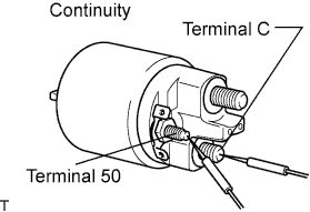
Check the pull-in coil for open circuit.
-
Using an ohmmeter, check that there is continuity between terminal 50 and C.
If there is no continuity, replace the magnet starter switch.
-
-
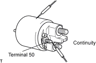
Check whether the holding coil has an open circuit.
-
Using an ohmmeter, check that there is continuity between terminal 50 and the switch body.
If there is no continuity, replace the magnet starter switch.
-
-