FUEL TEMPERATURE SENSOR INSTALLATION

-
INSTALL FUEL TEMPERATURE SENSOR
-
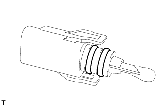
Install 2 new O-rings to the fuel temperature sensor.
-
Install the fuel temperature sensor.
-
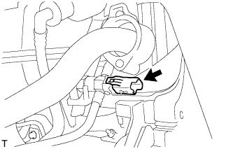
Connect the sensor connector.
-
Install the fuel temperature sensor to the cylinder head cover.
-
-
INSTALL AIR CLEANER CASE
-
Install the air cleaner case, and connect the 2 wire harness clamps.
-
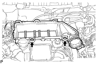
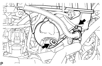
Using a "torx" socket wrench, install the air cleaner case with the 2 screws.
- Torque:
- 5.0 N*m { 51 kgf*cm, 44 in.*lbf }
-
-
INSTALL PRIMING PUMP BRACKET
-
Install the priming pump bracket.
-
Install the priming pump bracket to the air cleaner case.
-
-
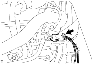
INSTALL TURBO PRESSURE SENSOR
-
Install the turbo pressure sensor with the screw.
- Torque:
- 4.0 N*m { 41 kgf*cm, 35 in.*lbf }
-
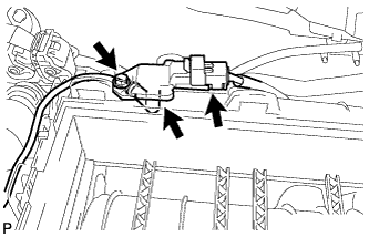
Connect the turbo pressure sensor connector and hose.
-
-
INSTALL INLET AIR CLEANER NO.2
-
Install the inlet air cleaner No.2.
-
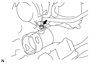
Using a "torx" socket wrench, install the inlet air cleaner No.2 with the screw.
- Torque:
- 5.0 N*m { 51 kgf*cm, 44 in.*lbf }
-
-
INSTALL INLET AIR CLEANER
-
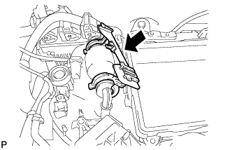
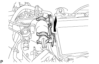
Install inlet air cleaner.
-
-
INSTALL ENGINE ROOM RELAY BLOCK
-
Connect the 3 wire harness clamps.
-
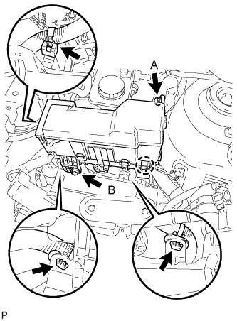
Engage the claw and install the engine room relay block with the 2 bolts.
- Torque:
- Bolt A
- 8.4 N*m { 86 kgf*cm, 74 in.*lbf }
- Bolt B
- 5.4 N*m { 55 kgf*cm, 48 in.*lbf }
-
-
INSTALL MASS AIR FLOW METER
-
Apply a light coat of engine oil to a new O-ring.
-
Install the O-ring to the mass air flow meter.
-
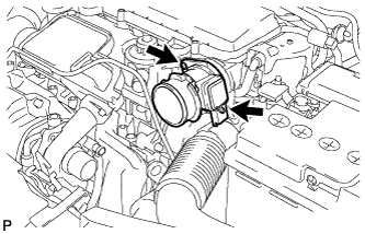
Using a "torx" socket wrench, install the mass air flow meter with the 2 screws.
- Torque:
- 3.5 N*m { 36 kgf*cm, 31 in.*lbf }
-
Connect the mass air flow meter connector.
-
-
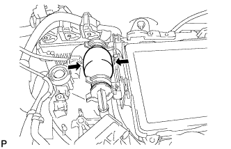
INSTALL AIR HOSE
-
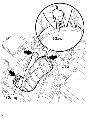
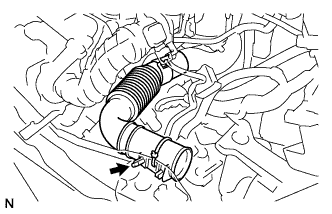
Install the air hose with the clamp and a new clip.
- Torque:
- Clamp
- 5.0 N*m { 51 kgf*cm, 44 in.*lbf }
-
-
INSTALL AIR CLEANER CAP
-
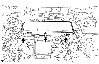
Using a "torx" socket wrench, install the air cleaner cap with the 3 screws.
- Torque:
- 5.0 N*m { 51 kgf*cm, 44 in.*lbf }
-
-
INSTALL ENGINE COVER
-
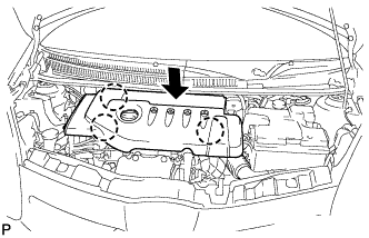
Align the 3 claws to install the engine cover.
-
-
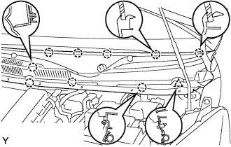
INSTALL COWL TOP PANEL OUTER
-
Install the cowl top panel outer with the 10 bolts.
- Torque:
- 9.2 N*m { 94 kgf*cm, 81 in.*lbf }
-
-
INSTALL FRONT WIPER MOTOR AND LINK ASSEMBLY
-
Connect the connector.
-
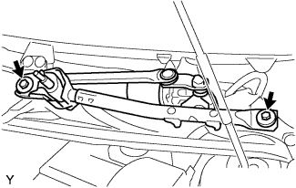
Install the front wiper motor and link assembly with the 2 bolts.
- Torque:
- 13 N*m { 127 kgf*cm, 9 ft.*lbf }
-
-
INSTALL COWL TOP VENTILATOR LOUVER RH
-
Connect the washer hose.
-

Engage the 8 claws and install the cowl top ventilator louver RH.
-
Install the clip.
-
-
INSTALL COWL TOP VENTILATOR LOUVER LH
-
Connect the washer hose.
-
Engage the 9 claws and install the cowl top ventilator louver LH.
-
Install the clip.
-
-
INSTALL HOOD TO COWL TOP SEAL

-
Engage the 8 clips and install the hood to cowl top seal.
-
-
INSTALL FRONT WIPER ARM LH
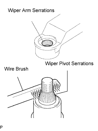
-
Scrape any metal powder off the serrated part of the wiper arm with a round file or equivalent (when reinstalling).
-
Clean the wiper pivot serrations with a wire brush.
-
Operate the wiper, then stop the windshield wiper motor assembly in the automatic stop position.
-
Provisionally install the front wiper main arm with the nut.
-
Install the front wiper secondary arm onto the front wiper motor and link assembly.
-
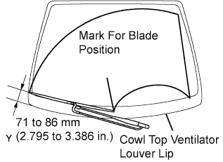
Align the blade tip with the mark on the windshield glass, as shown in the illustration.
-
Tighten the nut of the front wiper main arm.
- Torque:
- 21 N*m { 209 kgf*cm, 15 ft.*lbf }
-
-
INSTALL FRONT WIPER HEAD CAP
-
Engage the claw and install the front wiper arm head cap.
-
-
CONNECT BATTERY TO NEGATIVE BATTERY TERMINAL
-
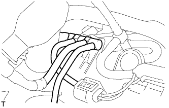
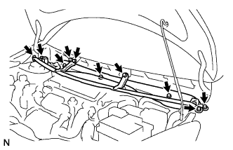
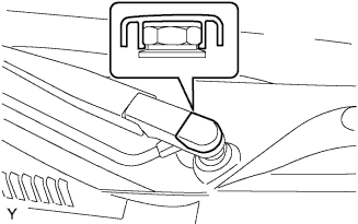
BLEED FUEL SYSTEM
-
Using the hand pump indicated by the arrows in the illustration, bleed the fuel system. Continue pumping until pumping becomes difficult.
-
-
CHECK FOR FUEL LEAKS
-
Check that there are no leaks from any part of the fuel system when the engine is stopped.
If there is fuel leakage, repair or replace parts as necessary.
-
Start the engine and check that there are no leaks from any part of the fuel system.
If there is fuel leakage, repair or replace parts as necessary.
-
Depress the accelerator pedal and rev up the 4000 rpm. After driving the vehicle, check for fuel leakage.
If there is excessive fuel leakage, repair or replace parts as necessary.
-