WATER PUMP INSTALLATION

-
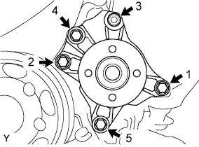
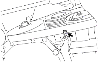
INSTALL ENGINE WATER PUMP ASSEMBLY
-
Install and uniformly tighten the 5 bolts, water pump assembly and the water pump gasket in the sequence shown in the illustration.
- Torque:
- 28 N*m { 286 kgf*cm, 21 ft.*lbf }
-
-
INSTALL WATER PUMP PULLEY
-
Using SST, install the water pump pulley with the 4 bolts.
- SST
- 09960-10010 ( 09962-01000, 09963-00600 )
- Torque:
- 14 N*m { 143 kgf*cm, 10 ft.*lbf }
-
-
INSTALL GENERATOR ASSEMBLY
-
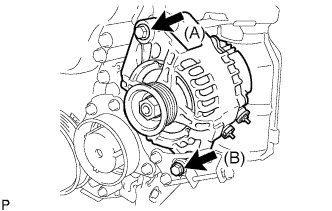
Install the generator with the 2 bolts.
- Torque:
- Bolt (A)
- 54 N*m { 551 kgf*cm, 40 ft.*lbf }
- Bolt (B)
- 34 N*m { 347 kgf*cm, 25 ft.*lbf }
-
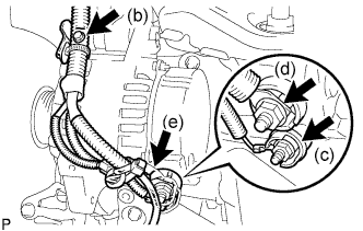
Install the wire harness clamp with the bolt.
- Torque:
- 8.4 N*m { 85 kgf*cm, 74 in.*lbf }
-
Install the generator wire with the nut to the terminal D.
- Torque:
- 4.5 N*m { 46 kgf*cm, 40 in.*lbf }
-
Install the generator wire with the nut to the terminal B.
- Torque:
- 9.0 N*m { 92 kgf*cm, 80 in.*lbf }
-
Install the terminal cap.
-
-
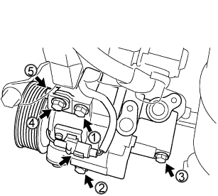
DISCONNECT COMPRESSOR AND MAGNETIC CLUTCH (w/ Air Conditioning)
-
Provisionally tighten the compressor and magnetic clutch with the 3 bolts.
-
Provisionally tighten compressor stay No. 1 with the bolt and nut.
-
Tighten the compressor and magnetic clutch with the 4 bolts and nut.
- Torque:
- 24.5 N*m { 250 kgf*cm, 18 ft.*lbf }
Note
Tighten the bolts in the sequence order shown in the illustration to install the compressor and magnetic clutch.
-
Connect the connector.
-
-
INSTALL FAN AND GENERATOR V BELT
-

Text in Illustration *1 Generator Pulley *2 Idle Pulley *3 Compressor Pulley *4 Crankshaft Pulley *a No Measurable Clearance *b Specified Point *c w/ Air Conditioning System *d w/o Air Conditioning System Install the fan and generator V belt.
-
Loosely tighten the B bolt until there is no measurable clearance.
-
Turn the C bolt to adjust tension of the fan and generator V belt. Click here
-
Inspect the fan and generator V belt.
-
Tighten the B bolt.
- Torque:
- 34 N*m { 347 kgf*cm, 25 ft.*lbf }
-
Tighten the A bolt.
- Torque:
- 49 N*m { 500 kgf*cm, 36 ft.*lbf }
-
Visually check the generator wiring and listen for abnormal noise.
-
-
ADD ENGINE COOLANT
-
Connect the engine side radiator outlet hose .
-
Install the cylinder block drain cock plug.
- Torque:
- 20 N*m { 204 kgf*cm, 15 ft.*lbf }
-
Pour engine coolant into the radiator assembly until it is full.
Capacity Specification Capacity except Tropic Spec 4.0 liters (4.2 US qts, 3.5 Imp qts) for Tropic Spec 4.4 liters (4.6 US qts, 3.9 Imp qts) Note
Do not substitute water for engine coolant.
Tech Tips
-
Use of improper engine coolant may damage the engine cooling system.
-
Use only Toyota Super Long Life Coolant or similar high quality ethylene glycol based non-silicate, non-amine, non-nitrite, and non-borate engine coolant with long-life hybrid organic acid technology (coolant with long-life hybrid organic acid technology consists of a combination of low phosphates and organic acids).
-
-
Check the engine coolant level inside the radiator assembly by pressing the inlet and outlet radiator hoses several times by hand. If the engine coolant level goes down, add engine coolant.
-
Install the radiator cap sub-assembly securely.
-
Slowly pour engine coolant into the radiator reservoir until it reaches the FULL line.
-
Bleed air from the cooling system.
-
Warm up the engine until the thermostat opens.
While the thermostat is open, circulate the coolant for several minutes.
-
The thermostat open timing can be confirmed by pressing the outlet radiator hose by hand, and checking when the coolant starts to flow inside the hose.
-
Maintain the engine speed at 2500 to 3000 rpm and warm up the engine until the cooling fan operates.
-
Press the outlet radiator hose and inlet radiator hose several times by hand to bleed air.
CAUTION:
When pressing the radiator hoses:
-
Wear protective gloves.
-
Be careful as the radiator hoses are hot.
-
Keep your hands away from the radiator fan.
-
-
-
Stop the engine and wait until the coolant cools down.
-
If the engine coolant level is below the full level, perform steps (c) through (h) and repeat the operation until the engine coolant level stays the full level.
-
Recheck the engine coolant level inside the radiator reservoir tank assembly. If it is below the full level, add engine coolant.
-
-
INSPECT COOLANT LEAK
CAUTION:
To avoid the danger of being burned, do not remove the radiator cap sub-assembly while the engine and radiator assembly are still hot. Thermal expansion will cause hot engine coolant and steam to blow out from the radiator assembly.
-
Fill the radiator assembly with engine coolant and attach a radiator cap tester.
-
Pump the tester to 137 kPa (1.4 kgf*cm2 , 19.9 psi), then check that the pressure does not drop. If the pressure drops, check the hoses, radiator assembly and water pump assembly for leakage. If there are no signs or traces of external engine coolant leakage, check the heater core, cylinder block and head.
-
-
INSTALL FRONT BUMPER COVER