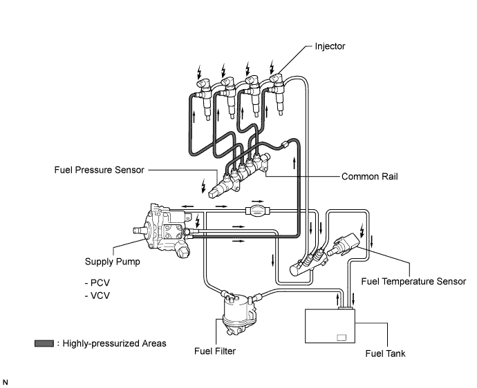
FUEL SYSTEM SYSTEM DIAGRAM

-
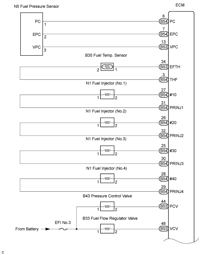
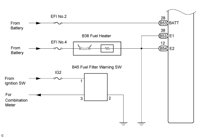
FUEL SYSTEM WIRING DIAGRAM
-
COMMON RAIL SYSTEM DESCRIPTION
-
COMMON RAIL SYSTEM:
The common rail system uses highly-pressurized fuel for improved fuel economy and to provide robust engine power, while suppressing engine vibration and noise.
This system stores fuel, which has been pressurized and supplied by the supply pump, in the common rail.
By storing fuel at high-pressure, the common rail system can provide fuel at stable fuel injection pressures, regardless of the engine speed or engine load.
The ECM provides an electric current to the solenoid valve in the injector, to regulate the fuel injection timing and volume, and also monitors the internal fuel pressure of the common rail using the fuel pressure sensor.
The ECM causes the supply pump to supply the fuel necessary to obtain the target fuel pressure, approximately 22 to 160 MPa (220 to 1,600 bars, 3,191 to 23,205 psi).
-
-
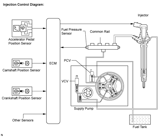
INJECTION CONTROL SYSTEM DESCRIPTION
The ECM controls the fuel injection system by using the injectors and supply pump. The ECM regulates the fuel injection volume and fuel injection timing by controlling both the duration and timing of energization to the injector. The ECM regulates injection pressure by controlling the PCV (Pressure Control Valve) located in the supply pump.
The feed pump is used to pump fuel from the fuel tank to the supply pump.
-
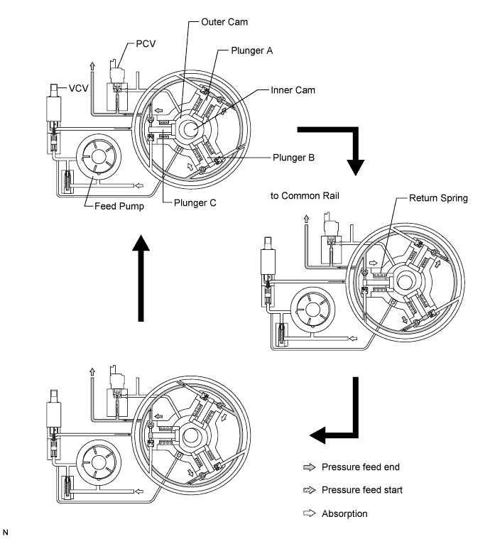
SUPPLY PUMP OPERATION SYSTEM DESCRIPTION
When the eccentric-shaft-shaped inner cam rotates, the outer cam pushes up plunger A, which pressure-feeds the fuel from the plunger to the common rail. When the pressure feed stroke of plunger A comes to an end, plunger B starts to pressure-feed the fuel. At the same time, plunger C is pushed back due to the reaction force of the spring and absorbs the fuel in the plunger. By using the three plungers to repeat these strokes in order, a stable pressure feed of fuel can be performed constantly.
The ECM calculates a target pressure in the common rail based on the engine condition. The ECM then sends a signal to the VCV (Fuel Flow Regulator Valve) to control the amount of fuel that will be absorbed in a plunger. The control signal is DUTY.
-
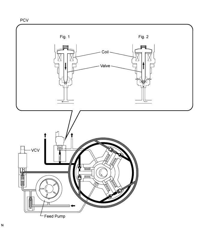
PCV (PRESSURE CONTROL VALVE) OPERATION SYSTEM DESCRIPTION
When the ignition switch is turned to the ON position, the coil attracts the valve based on the signals from the ECM to close the fuel path. (Fig.1)
When the ECM determines that the fuel pressure in the common rail exceeds the specified value based on a signal from the fuel pressure sensor in the common rail, the ECM controls the current applied to the PCV coil to open the valve. Then, the fuel pressure in the common rail will decrease to the specified value. (Fig. 2)
When the ignition switch is turned off, the current applied to the coil in the PCV will be shut off and fuel pressure opens the valve.
When the fuel pressure becomes lower than the spring force, the valve will close.
The PCV is normaly closed by return spring. This means that when no signal is applied to the coil, the pressure in the common rail will be not 0. In this way the valve provide a minimum pressure of 5 MPa (50 bars, 725 psi).
When a current is applied to the coil, an additional force is added to that of the spring. The control signal is DUTY, and the average current is 0.6 A with peak of 2 A. The injector needle returns spring tension is set to 7 MPa (70 bars, 1,015 psi). This pressure is higher than the pressure of PCV, which is set at 5 MPa (50 bars, 725 psi). In this way the injector will not open if PCV does not operate.
-
VCV (FUEL FLOW REGULATOR VALVE) OPERATION SYSTEM DESCRIPTION
Tech Tips
The ECM controls the VCV operation to regulate the fuel volume that is pumped by the supply pump to the common rail.
-
Small opening of the VCV:
-
When the opening of the VCV is small, the volume of fuel supplied to the high pressure pump is small. This is done by restricting the flow to the high pressure pump.
-
-
Large opening of the VCV:
-
When the opening of the VCV is large, the fuel suction path is kept wide. Therefore, the fuel volume supplied to the fuel pump is increased.
-
-