FUEL TANK INSTALLATION

-
INSTALL FUEL TANK PROTECTOR LOWER CENTER
-
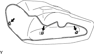
Install the fuel tank protector lower center with the 3 screws.
-
-
INSTALL FUEL TANK TO FILLER PIPE HOSE
-
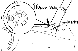
Align the mark on the hose with the mark on the fuel tank, install the fuel tank to filler pipe hose with the hose clamp bolt as shown in the illustration.
-
-
INSTALL FUEL TANK MAIN TUBE SUB-ASSEMBLY
-
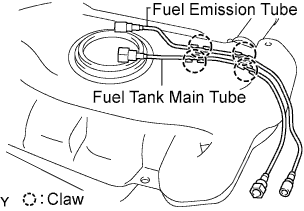
Install the fuel tank main tube and fuel emission tube with the 4 claws.
-
-
INSTALL FUEL TANK ASSEMBLY
-
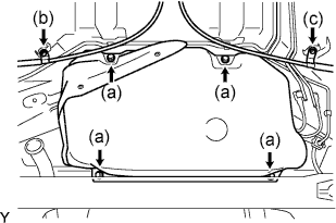
Install the fuel tank with 4 new bolts.
- Torque:
- 14 N*m { 146 kgf*cm, 11 ft.*lbf }
-
Install the parking brake cable No.2 with the bolt.
- Torque:
- 6.0 N*m { 61 kgf*cm, 53 in.*lbf }
-
Install the parking brake cable No.3 with the bolt.
- Torque:
- 6.0 N*m { 61 kgf*cm, 53 in.*lbf }
-
-
CONNECT FUEL TANK FILLER PIPE SUB-ASSEMBLY
-
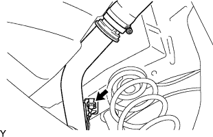
Install the fuel tank filler pipe with the bolt.
- Torque:
- 20 N*m { 204 kgf*cm, 15 ft.*lbf }
-
-
CONNECT FUEL TANK MAIN TUBE SUB-ASSEMBLY
-
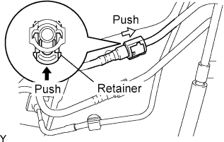
Connect the fuel tank main tube.
-
Push in the fuel tube connector to the pipe and push up the retainer so that the claws engage.
Note
-
Check if there is any damage or foreign objects on the connected part.
-
After connecting, check that the fuel tube connector and the pipe are securely connected by trying to pull them apart.
-
-
-
-
CONNECT FUEL EMISSION TUBE SUB-ASSEMBLY NO.1
-
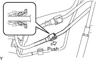
Connect the fuel emission tube.
-
Push the fuel tube connector into the pipe until the fuel tube connector makes a "click" sound.
Note
-
Check if there is any damage or foreign objects on the connected part.
-
After connecting, check that the fuel tube connector and the pipe are securely connected by trying to pull them apart.
-
-
-
-
INSTALL EXHAUST PIPE ASSEMBLY FRONT
-
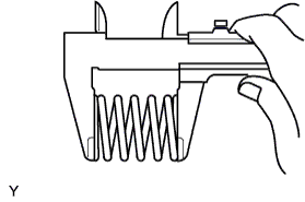
Using vernier calipers, measure the free length of the compression spring.
Minimum length 40.5 mm (1.594 in.)
-
If the length is not as specified, replace the compression spring.
-
-
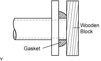
Using a plastic hammer and a wooden block, tap in a new exhaust pipe gasket until its surface is flush with the exhaust manifold.
Note
-
Be sure to install the exhaust pipe gasket in the correct direction.
-
Do not damage the outer surface of the exhaust pipe gasket.
-
Do not reuse the exhaust pipe gasket.
-
Do not push in the gasket with the exhaust pipe when connecting it.
-
-
Install the exhaust front pipe assembly and a new exhaust pipe gasket with the 2 compression springs and 2 bolts.
- Torque:
- 45 N*m { 459 kgf*cm, 33 ft.*lbf }
-
Install the exhaust pipe No.4 support.
-
Install the bolt and clamp.
- Torque:
- 32 N*m { 326 kgf*cm, 24 ft.*lbf }
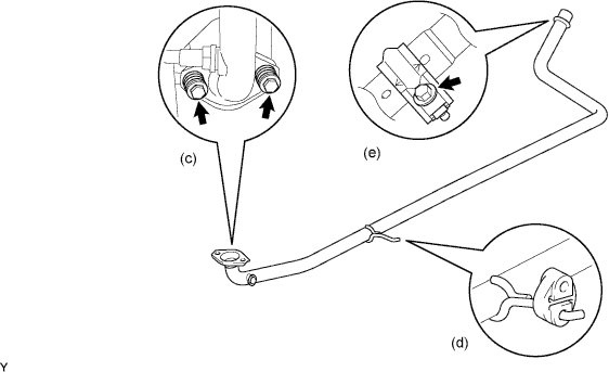
Note
-
Clamp marks and stamping should be aligned.
-
-
INSTALL FUEL PUMP ASSEMBLY
-
Install a new gasket onto the fuel tank.
-
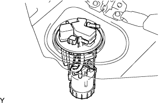
Set the fuel pump assembly to the fuel tank.
Note
The arm of the sender gauge should not be bent.
-
-
INSTALL FUEL PUMP GAUGE RETAINER
-
Align the end of the threads of a new fuel pump gauge retainer with that of the fuel tank.
-
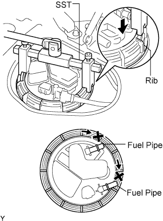
Using a socket wrench (6 mm), set SST to the fuel pump gauge retainer.
- SST
- 09808-14020 ( 09808-01410, 09808-01420, 09808-01430 )
Note
-
Use SST. Do not use any other tools such as a screwdriver.
-
As the fuel pipes are located on the track of the SST, the SST should be reset a few times to prevent it from making contact with the pipes when installing the fuel pump gauge retainer.
Tech Tips
Fit the rib on the fuel pump gauge retainer into the cutout of the SST.
-
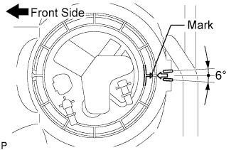
While holding the fuel pump assembly by hand, use SST to tighten the fuel pump gauge retainer one and half turns so that the mark on the retainer is within the indicated range in the illustration.
-
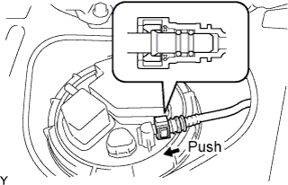
Connect the fuel tank main tube sub-assembly.
-
Push in the tube connector to the pipe until the tube connector makes a "click" sound.
Note
-
Check if there is any damage or foreign objects on the connected part of the fuel pipe.
-
After connecting, check that the fuel tube connector and the pipe are securely connected by pulling on them.
-
-
-
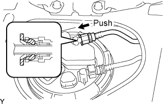
Connect the fuel emission tube sub-assembly No.1.
-
Push in the tube connector to the pipe until the tube connector makes a "click" sound.
Note
-
Check if there is any damage or foreign objects on the connected part of the fuel pipe.
-
After connecting, check that the fuel tube connector and the pipe are securely connected by pulling on them.
-
-
-
-
INSTALL REAR FLOOR SERVICE HOLE COVER
-
Install the rear floor service hole cover with new butyl tape.
-
-
INSTALL REAR SEAT CUSHION ASSEMBLY
-
Separate seat type Click here
-
Bench seat type Click here
-
-
ADD FUEL
-
CONNECT CABLE TO NEGATIVE BATTERY TERMINAL
-
CHECK FOR FUEL LEAKS
-
When using the intelligent tester.
-
Connect the intelligent tester to the DLC3.
-
Turn the ignition switch to the ON position and intelligent tester main switch on.
Note
Do not start the engine.
-
Select the Active Test mode on the intelligent tester.
Tech Tips
Refer to the intelligent tester operator's manual for further details.
-
-
Check that there are no fuel leaks anywhere on the fuel system after doing maintenance.
-