ENGINE UNIT REASSEMBLY

-
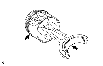
INSTALL W/ PIN PISTON SUB-ASSEMBLY
-
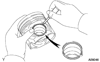
Install a new snap ring on one side of the piston pin hole.
-
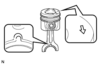
Align the front marks of the piston and connecting rod, and push in the piston pin by hand.
-
Install a new snap ring on the other side of the piston pin hole.
-
-
INSTALL OIL NOZZLE SUB-ASSEMBLY
-
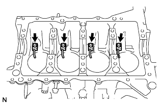
Using a hexagon socket wrench, install the 4 oil nozzles with the 4 bolts.
- Torque:
- 20 N*m { 204 kgf*cm, 15 ft.*lbf }
-
-
INSTALL CRANKSHAFT BEARING
-
Install the crankshaft lower bearings.
-
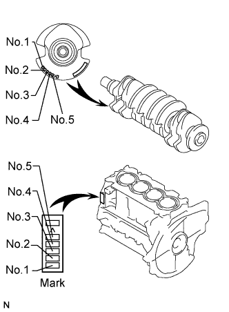
Select new crankshaft lower bearings.
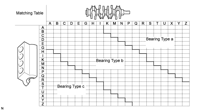
Tech Tips
Check the marks on the crankshaft and cylinder block for each cylinder. Refer to the matching table to select the bearing.
-
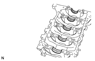
Align the crankshaft lower bearings with the crankshaft bearing cap lower housing and install the crankshaft lower bearings.
Note
Do not apply engine oil to the contact surfaces of the bearings and crankshaft bearing cap lower housing.
-
-
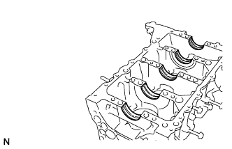
Align the crankshaft upper bearings with the cylinder block and install the crankshaft upper bearings.
Note
Do not apply engine oil to the bearings and their contact surfaces of the bearings and cylinder block.
Tech Tips
There is only one type of the crankshaft upper bearing.
-
-
INSTALL CRANKSHAFT
-
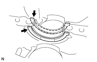
Install the 2 crankshaft thrust washers onto the No.3 journal position of the cylinder block.
-
Apply engine oil to the sliding surface of the crankshaft bearings (upper) and install the crankshaft.
-
-
INSTALL PISTON RING SET
-
Install the oil ring.
-
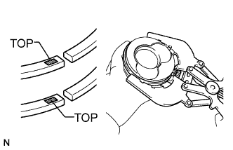
Using a piston ring expander, install the No.2 compression ring and No.1 compression ring with the identification marks (TOP) facing upward.
-
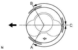
Install the rings so that each end faces as shown in the illustration.
Ring A No.1 compression ring B No.2 compression ring C Oil ring
-
-
INSTALL CONNECTING ROD BEARING
-
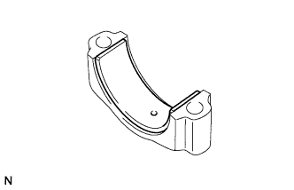
Align the connecting rod bearings with the connecting rod bearing caps and install the connecting rod bearings.
Note
Do not apply engine oil to the bearings and their contact surfaces.
-
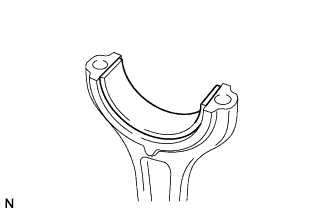
Align the connecting rod bearings with the connecting rods and install the connecting rod bearings.
Note
Do not apply engine oil to the bearings and their contact surfaces.
-
-
INSTALL CONNECTING ROD SUB-ASSEMBLY
-
Make sure that the compression rings and oil ring are installed in the correct direction respectively.
Ring A No.1 compression ring B No.2 compression ring C Oil ring -
Apply engine oil to the sliding surfaces of the piston and connecting rod sub-assembly.
-
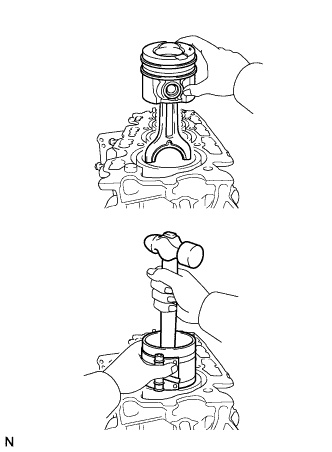
Using a piston ring compressor, correctly push the numbered piston and connecting rod assembly into each cylinder with the front mark of the piston facing forward.
-
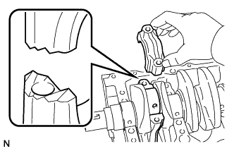
Align the connecting rod bearing cap shear end with the connecting rod shear end and install the connecting rod bearing caps.
-
Apply a light coat of engine oil to the threads and under the heads of the connecting rod cap bolts.
-
Using a ''torx'' socket wrench (E10), install the connecting rod bearing cap bolts.
- Torque:
- 10 N*m { 102 kgf*cm, 7 ft.*lbf }
-
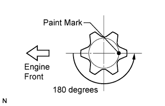
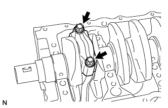
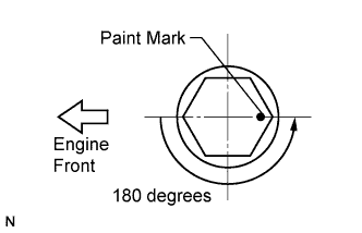
Mark the front of the connecting rod bearing cap bolts with paint.
-
Loosen the connecting rod bearing cap bolts by an additional 180 degrees as shown in the illustration.
-
Retighten the connecting rod bearing cap bolts.
- Torque:
- 10 N*m { 102 kgf*cm, 7 ft.*lbf }
-
Mark the front of the connecting rod bearing cap bolts with paint.
-
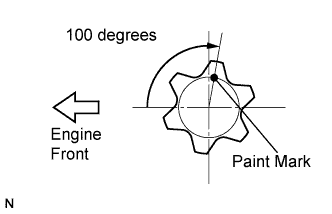
Retighten the connecting rod bearing cap bolts by an additional 100 degrees as shown in the illustration.
-
-
INSTALL CRANKSHAFT BEARING CAP HOUSING
-
Apply seal packing to the cylinder block as shown in the illustration.
Note
Install the cylinder block within 5 minutes after applying seal packing.
-
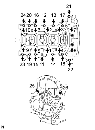
Temporarily install the crankshaft bearing cap housing with the 26 bolts.
-
Tighten the 10 bolts as shown in the illustration (in order 1 to 10).
- Torque:
- 10 N*m { 102 kgf*cm, 7 ft.*lbf }
-
Tighten the 14 bolts as shown in the illustration (in order 11 to 24).
- Torque:
- 6.0 N*m { 61 kgf*cm, 53 in.*lbf }
-
Tighten the 2 bolts as shown in the illustration (in order 25 to 26).
- Torque:
- 8.0 N*m { 82 kgf*cm, 71 in.*lbf }
-
Mark the front of the 10 bolts with paint.
-
Loosen the 10 bolts by an additional 180 degrees as shown in the illustration (in order 10 to 1).
-
Retighten the 10 bolts as shown in the illustration (in order 1 to 10).
- Torque:
- 30 N*m { 306 kgf*cm, 22 ft.*lbf }
-

Mark the front of the 10 bolts with paint.
-
Retighten the 10 bolts by an additional 140 degrees as shown in the illustration (in order 1 to 10).
-
Retighten the 14 bolts as shown in the illustration (in order 11 to 24).
-
Check that the crank shaft moves smoothly.
-

Install the crankshaft bearing cap housing bolt covers.
-
-
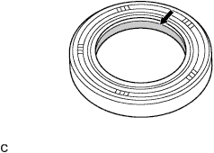
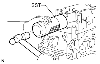
INSTALL CRANK REAR OIL SEAL
-
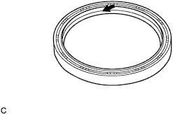
Apply engine oil to the lip of a new oil seal.
-
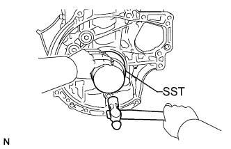
Using SST, tap the oil seal straight in.
- SST
- 09951-01000
-
-
INSTALL OIL PUMP ASSEMBLY
-
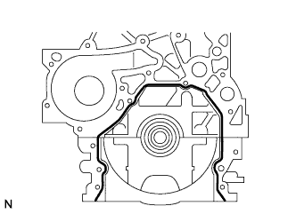
Apply seal packing to the cylinder block as shown in the illustration.
Seal packing Part No. 08826-00080 or equivalent Note
Install the oil pump assembly within 3 minutes after applying packing.
-
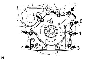
Temporarily install the oil pump assembly with the 8 bolts.
-
Tighten the 8 bolts in the order shown in the illustration.
- Torque:
- 5.0 N*m { 51 kgf*cm, 44 in.*lbf }
-
Retighten the 8 bolts in the order shown in the illustration.
- Torque:
- 9.0 N*m { 92 kgf*cm, 80 in.*lbf }
-
-
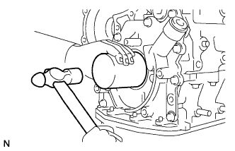
INSTALL OIL STRAINER SUB-ASSEMBLY
-
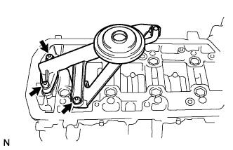
Install a new gasket to the oil strainer sub-assembly.
-
Using a hexagon socket wrench, install the oil strainer sub-assembly with the 3 bolts.
- Torque:
- 7.0 N*m { 71 kgf*cm, 62 in.*lbf }
-
-
INSTALL OIL PAN SUB-ASSEMBLY
-
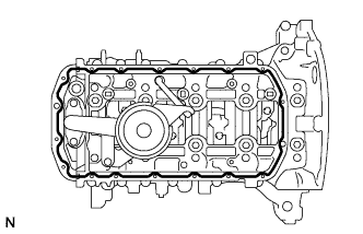
Apply seal packing to the cylinder block as shown in the illustration.
Seal packing Part No. 08826-00080 or equivalent Note
Install the oil pan sub-assembly within 5 minutes after applying packing.
-
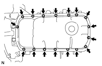
Install the oil pan sub-assembly with the 15 bolts and 2 nuts.
- Torque:
- 10 N*m { 102 kgf*cm, 7 ft.*lbf }
-
-
INSTALL CRANK OIL SEAL
-
Apply engine oil to the lip of a new oil seal.
-
Using SST, tap the oil seal straight in.
- SST
- 09309-37010
-
-
INSTALL OIL CHECK VALVE
-
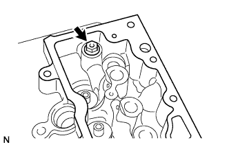
Install the oil check valve.
- Torque:
- 25 N*m { 255 kgf*cm, 18 ft.*lbf }
-
-
INSTALL OIL PRESSURE REGULATOR
-
Install the oil pressure regulator.
-
-
INSTALL VALVE GUIDE BUSH
-
Install the intake valve guide bush.
-
Heat the cylinder head to 80 to 100°C (176 to 212°F)
-
Using SST and a hammer, tap in new intake valve guide bushes to the specified protrusion height.
- SST
- 09201-10000 ( 09201-01050 )
-
-
Install the exhaust valve guide bush.
-
Heat the cylinder head to 80 to 100°C (176 to 212°F)
-
Using SST and a hammer, tap in new exhaust valve guide bushes to the specified protrusion height.
- SST
- 09201-10000 ( 09201-01050 )
-
-
-
INSTALL VALVE STEM OIL SEAL
-
Apply a light coat of engine oil to 8 new valve stem oil seals.
-
Using SST and a hammer, tap in the valve stem oil seals.
- SST
- 09201-77010
-
-
INSTALL VALVE
-
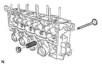
Install the exhaust valves.
-
Install the exhaust valve, inner compression spring and valve spring retainer.
-
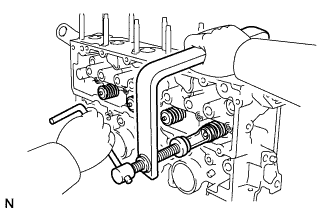
Using SST, compress the inner compression spring and place the 2 retainer locks around the valve stem.
- SST
- 09202-70020 ( 09202-00020, 09202-01010, 09202-01020, 90154-80004 )
-
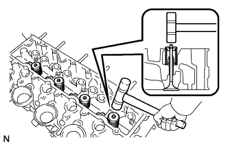
Using a plastic hammer, lightly tap the valve stem tip to ensure a proper fit.
Note
Do not damage the valve stem tip.
-
-

Install the intake valves.
-
Install the intake valve, inner compression spring and valve spring retainer.
-
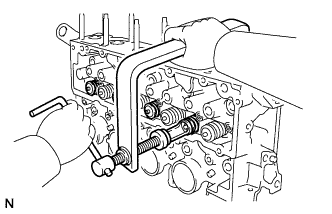
Using SST, compress the inner compression spring and place the 2 retainer locks around the valve stem.
- SST
- 09202-70020 ( 09202-00020, 09202-01010, 09202-01020, 90154-80004 )
-
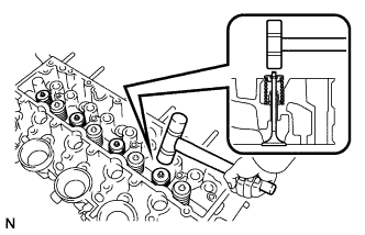
Using a plastic hammer, lightly tap the valve stem tip to ensure a proper fit.
Note
Do not damage the valve stem tip.
-
-
-
INSTALL CYLINDER HEAD SUB-ASSEMBLY
-
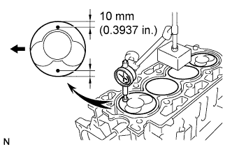
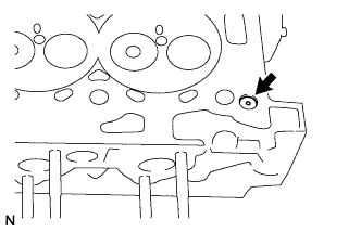
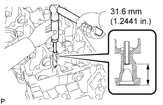
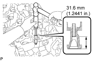
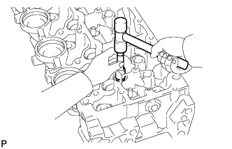
Check piston protrusions for each cylinder.
-
Find where the piston head protrudes most by slowly turning the crankshaft clockwise and counterclockwise.
-
Measure the piston protrusion at 2 places for each cylinder as shown in the illustration, marking a total of 8 measurements.
-
For the piston protrusion valve of each cylinder, use the average of the 2 measurements of each cylinder.
Protrusion 0.771 to 0.977 mm (0.0304 to 0.0385 in.) Maximum gap 0.10 mm (0.0039 in).
-
-
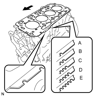
Select a new cylinder head gasket.
Tech Tips
There are 5 sizes of new cylinder head gaskets, marked (A), (B), (C), (D) or (E).
Cylinder head gasket thickness Mark Thickness A 1.35 mm (0.0531 in.) B 1.25 mm (0.0492 in.) C 1.30 mm (0.0512 in.) D 1.40 mm (0.0551 in.) E 1.45 mm (0.0571 in.)
-
Select the largest piston protrusion value from the measurements made, then select a new appropriate gasket according to the table below.
Piston protrusion Gasket size 0.771 to 0.820 mm (0.0304 to 0.0323 in.) Use A 0.6115 to 0.720 mm (0.0241 to 0.0283 in.) Use B 0.721 to 0.770 mm (0.0284 to 0.0303 in.) Use C 0.821 to 0.870 mm (0.0323 to 0.0343 in.) Use D 0.871 to 0.977 mm (0.0343 to 0.0385 in.) Use E
-
-
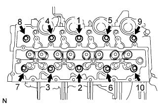
Temporarily install the cylinder head gasket, and cylinder head sub-assembly with the 10 bolts.
-
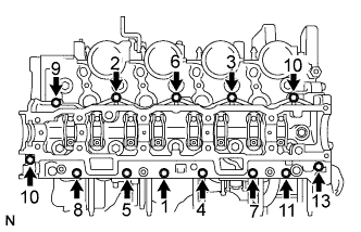
Using a ''torx'' socket wrench (E14), tighten the 10 bolts in the order shown in the illustration.
- Torque:
- 20 N*m { 204 kgf*cm, 15 ft.*lbf }
-
Retighten the 10 bolts in the order shown in the illustration.
- Torque:
- 40 N*m { 408 kgf*cm, 30 ft.*lbf }
-
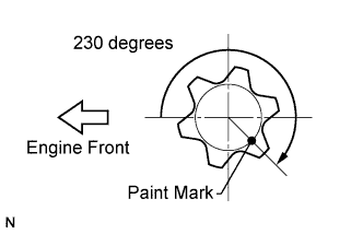
Mark the front of each cylinder head bolt with paint.
-
Retighten the bolts by 230 degrees in the order shown in the illustration.
-
Install the 8 valve lash adjusters and 8 valve rocker arms.
-
-
INSTALL CAMSHAFT BEARING CAP LOWER HOUSING
-
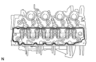
Apply seal packing to the cylinder head sub-assembly as shown in the illustration.
Seal packing Part No. 08826-00080 or equivalent Note
Install the camshaft bearing cap lower housing within 5 minutes after applying seal packing.
-
Temporarily install the camshaft bearing cap lower housing with the 13 bolts.
-
Tighten the bolts in the order shown in the illustration.
- Torque:
- 3.0 N*m { 31 kgf*cm, 27 in.*lbf }
-
Retighten the bolts in the order shown in the illustration.
- Torque:
- 10 N*m { 102 kgf*cm, 7 ft.*lbf }
-
-
INSTALL CAMSHAFT SUB-ASSEMBLY
-
Install the camshaft.
-
-
INSTALL CAMSHAFT BEARING CAP UPPER HOUSING
-
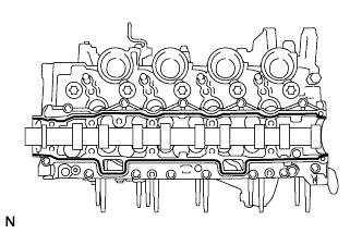
Apply seal packing to the camshaft bearing cap lower housing as shown in the illustration.
Seal packing Part No. 08826-00080 or equivalent Note
Install the camshaft bearing cap upper housing within 5 minutes after applying seal.
-
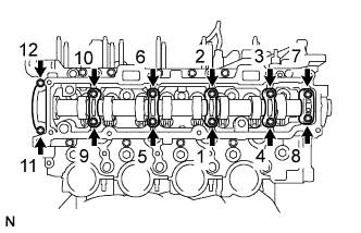
Temporarily install the camshaft bearing cap upper housing with the 12 bolts.
-
Tighten the bolts in the order shown in the illustration.
- Torque:
- 3.0 N*m { 31 kgf*cm, 27 in.*lbf }
-
Retighten the bolts in the order shown in the illustration.
- Torque:
- 10 N*m { 102 kgf*cm, 7 ft.*lbf }
-
-
INSTALL CAM OIL SEAL
-
Apply engine oil to the lip of a new oil seal.
-
Using SST, tap the oil seal straight in.
- SST
- 09631-20081
-
-
INSTALL TIMING BELT IDLER SUB-ASSEMBLY
-
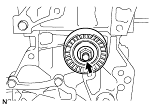
Install the timing belt idler sub-assembly with the nut.
- Torque:
- 35 N*m { 357 kgf*cm, 26 ft.*lbf }
-
-
INSTALL INJECTION PUMP BRACKET
-
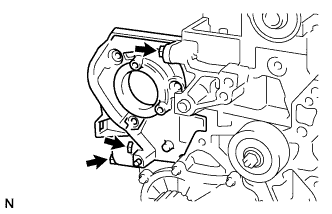
Install the injection pump bracket with the 3 bolts.
- Torque:
- 22 N*m { 224 kgf*cm, 16 ft.*lbf }
-
-
INSTALL CAMSHAFT DRIVE PULLEY
-
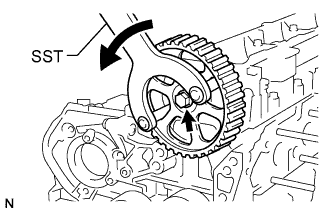
Temporarily install the camshaft drive pulley with the bolt.
-
Using SST, tighten the bolt.
- SST
- 09960-10010 ( 09962-01000, 09963-01000 )
- Torque:
- 20 N*m { 204 kgf*cm, 15 ft.*lbf }
-
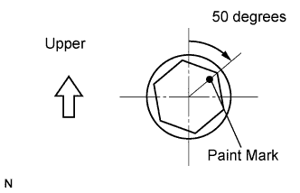
Mark the top surfaces of the bolts with paint.
-
Retighten the bolts by an additional 50 degrees as shown in the illustration.
-
-
INSTALL WATER PUMP ASSEMBLY
-
Install a new gasket to the water pump.
-
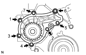
Install the water pump with the 7 bolts in the order shown in the illustration.
- Torque:
- 5.0 N*m { 51 kgf*cm, 44 in.*lbf }
-
Retighten the 7 bolts in the order shown in the illustration.
- Torque:
- 10 N*m { 102 kgf*cm, 7 ft.*lbf }
-