ENGINE UNIT DISASSEMBLY

-
REMOVE WATER PUMP ASSEMBLY
-
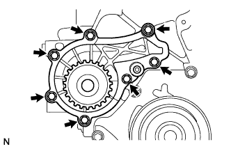
Remove the 7 bolts and water pump.
-
-
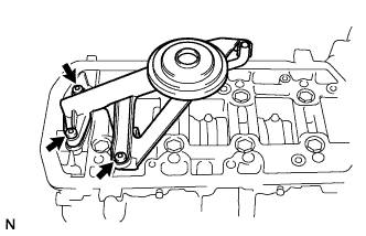
REMOVE CAMSHAFT DRIVE PULLEY
-
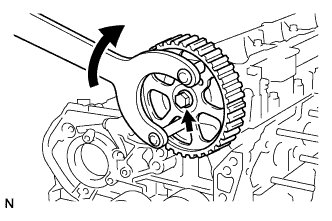
Using SST, remove the bolt and camshaft drive pulley.
- SST
- 09960-10010 ( 09962-01000, 09963-01000 )
-
-
REMOVE INJECTION PUMP BRACKET
-
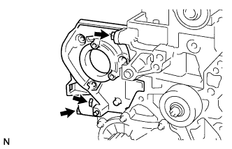
Remove the 3 bolts and injection pump bracket.
-
-
REMOVE TIMING BELT IDLER SUB-ASSEMBLY
-
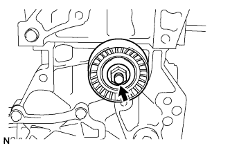
Remove the nut and timing belt idler sub-assembly.
-
-
REMOVE CAMSHAFT BEARING CAP UPPER HOUSING
-
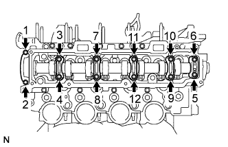
Using several steps, uniformly loosen and remove the camshaft bearing cap upper housing bolts in the order shown in the illustration.
-
-
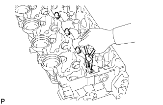
REMOVE CAMSHAFT SUB-ASSEMBLY
-
Remove the camshaft and oil seal.
-
-
REMOVE CAMSHAFT BEARING CAP LOWER HOUSING
-
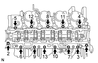
Using several steps, uniformly loosen and remove the camshaft bearing cap lower housing bolts in the order shown in the illustration.
-
Remove the 5 O-rings, 8 valve rocker arms and 8 valve lash adjusters.
-
-
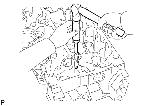
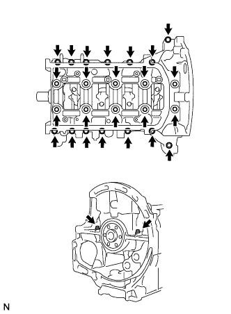
REMOVE CYLINDER HEAD SUB-ASSEMBLY
-
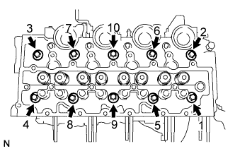
Using a ''torx'' socket wrench (E14), uniformly loosen and remove the cylinder head bolts in the order shown in the illustration.
-
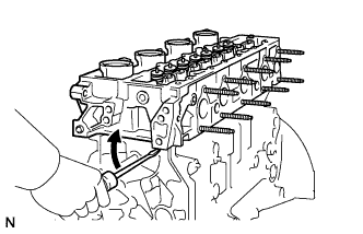
Remove the cylinder head sub-assembly and cylinder head gasket from the cylinder block assembly.
Tech Tips
Pry between the cylinder head and cylinder block with a screwdriver to lift off the cylinder head.
Note
Be careful not to damage the contact surfaces of the cylinder head and cylinder block.
-
-
CLEAN CYLINDER HEAD SUB-ASSEMBLY
-
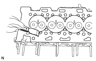
Using a scraper, clean the contact surface of the cylinder head.
-
-
CLEAN CYLINDER BLOCK SUB-ASSEMBLY
-
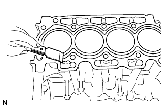
Using a scraper, clean the contact surface of the cylinder block.
-
-
REMOVE VALVE
-
Remove intake valve.
-
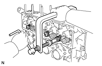
Using SST, remove the valve retainer locks, valve retainer springs, compression springs and intake valves.
- SST
- 09202-70020 ( 09202-00020, 09202-01010, 09202-01020, 90154-80004 )
-
-
Remove exhaust valve.
-
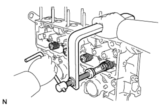
Using SST, remove the valve retainer locks, valve retainer springs, compression springs and exhaust valves.
- SST
- 09202-70020 ( 09202-00020, 09202-01010, 09202-01020, 90154-80004 )
-
-
-
REMOVE VALVE STEM OIL SEAL
-
Using needle-nose pliers, remove the valve stem oil seals.
-
-
REMOVE VALVE GUIDE BUSH
-
Heat the cylinder head to 80 to 100°C (176 to 212°F).
-
Using SST and a hammer, tap out the valve guide bushes.
- SST
- 09201-10000 ( 09201-01050 )
-
-
REMOVE OIL PRESSURE REGULATOR
-
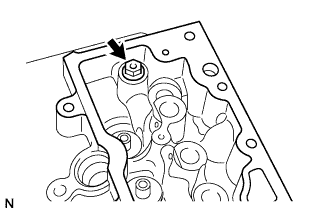
Remove the oil pressure regulator.
-
-
REMOVE OIL CHECK VALVE
-
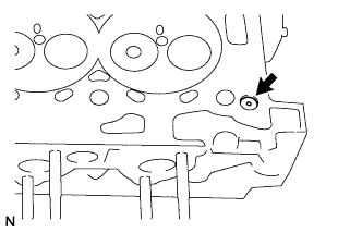
Remove the oil check valve.
-
-
INSPECT CYLINDER HEAD SUB-ASSEMBLY
-
Clean the surface to be checked.
-
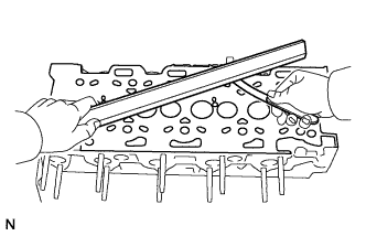
Using a straight edge and feeler gauge, measure the warpage on the contact surface.
Maximum warpage 0.05 mm (0.0020 in.) If the warpage is greater than the maximum value, replace the cylinder head sub-assembly.
-
-
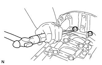
REMOVE OIL PAN SUB-ASSEMBLY
-
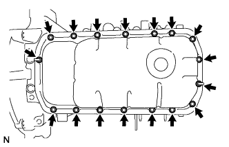
Remove the 2 nuts and 15 bolts.
-
Using an oil pan cutter, remove the oil pan sub-assembly from the cylinder block assembly.
- SST
- 09032-00100
-
-
REMOVE OIL STRAINER SUB-ASSEMBLY
-
Using a hexagon socket wrench, remove the 3 bolts, oil strainer sub-assembly and gaskets.
-
-
REMOVE OIL PUMP ASSEMBLY
-
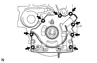
Remove the 8 bolts and oil pump assembly.
-
-
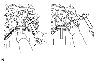
REMOVE CRANKSHAFT BEARING CAP HOUSING
-
Using a screwdriver, remove the 2 crankshaft bearing cap housing bolt covers.
-
Remove the 26 bolts, crankshaft bearing cap housing and oil seal.
-
Remove the crankshaft lower bearings.
-
-
REMOVE CONNECTING ROD BEARING CAP
-
Using a ''torx'' socket wrench (E10), remove the 2 bolts and connecting rod cap.
-
Remove the connecting rod bearing from the connecting rod cap.
-
-
REMOVE CONNECTING ROD SUB-ASSEMBLY
-
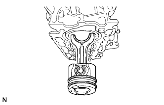
Push the connecting rod sub-assembly and remove the connecting rod and piston through the top of the cylinder block.
Tech Tips
Arrange the connecting rod sub-assembly for each cylinder.
-
Remove the connecting rod upper bearing.
-
-
INSPECT CRANKSHAFT
-
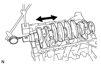
Using a dial indicator, measure the thrust clearance while moving the crankshaft back and forth.
Standard clearance 0.07 to 0.32 mm (0.0028 to 0.0126 in.)
-
-
REMOVE CRANKSHAFT
-
Remove the crankshaft.
-
Remove the crankshaft upper bearing.
-
-
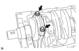
REMOVE OIL NOZZLE SUB-ASSEMBLY
-
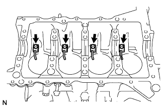
Using a hexagon socket wrench, remove the 4 bolts and 4 oil nozzles.
-
-
REMOVE PISTON RING SET
-
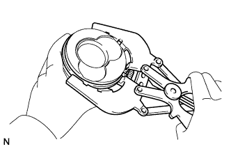
Using a piston ring expander, remove the No.1 compression ring, No.2 compression ring and oil ring.
-
-
REMOVE W/ PIN PISTON SUB-ASSEMBLY
-
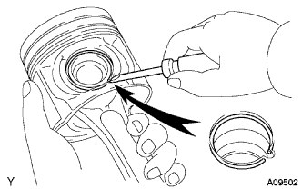
Using a screwdriver, pry off the snap rings from the piston.
-
Remove the piston pin and connecting rod.
-