ENGINE ON-VEHICLE INSPECTION

-
INSPECT ENGINE COOLANT
-
Remove the reservoir tank cap sub-assembly.
CAUTION:
To avoid the danger of being burned, do not remove the reservoir tank cap sub-assembly while the engine and radiator assembly are still hot. Thermal expansion will cause hot engine coolant and steam to blow out from the radiator assembly.
-
Check for any excessive deposit of rust or scale around the reservoir tank cap sub-assembly and radiator filler hole. The engine coolant should be free of oil.
-
If excessively dirty, replace the engine coolant.
-
-
Reinstall the reservoir tank cap sub-assembly.
-
-
INSPECT ENGINE OIL
-
Check for deterioration, traces of water, discoloring, or thinning. If the quality is visibly poor, replace the oil.
Oil grade API grade CF (Full Synthetic), ACEA A3/B3, SAE 5W-30 or 5W-40 is the best choice for your vehicle for good fuel economy and good starting in cold weather. Note
-
Only use full synthetic motor oil.
-
Do not use mineral motor oil.
-
The use of the genuine motor oil is recommended. Another motor oil matching quality can also be used.
-
-
-
INSPECT BATTERY
-
Check the battery for damage and deformation. If severe damage, deformation, or leakage is found, replace the battery.
-
Check the electrolyte level of each cell.
-
For maintenance-free batteries:
-
If the electrolyte level is below the lower line, replace the battery.
-
If the electrolyte level is above the lower line, check the battery voltage while cranking the engine.
-
If the voltage is less than 9.6 V, recharge or replace the battery.
Tech Tips
Before checking battery voltage, turn off all the electrical systems (headlights, blower motor, rear defogger, etc.).
-
-
For non-maintenance-free batteries:
-
If the electrolyte level is below the lower line, add distilled water to each cell. Then, recharge the battery and check the electrolyte gravity.
Standard gravity 1.25 to 1.29 at 20°C (68°F)
If the electrolyte level is above the lower line, check battery voltage while cranking the engine. If the voltage is less than 9.6 V, recharge or replace the battery.
Tech Tips
Before checking battery voltage, turn off all the electrical systems (headlights, blower motor, rear defogger, etc.).
-
-
-
-
INSPECT AIR CLEANER FILTER ELEMENT SUB-ASSEMBLY
-
Remove the air cleaner filter element from the air cleaner case.
-
Visually check that there is no dirt, clog and/or damage to the air cleaner filter element.
Tech Tips
If any dirt, clog and/or damage on the air cleaner filter element, replace it.
-
-
INSPECT DRIVE BELT
-
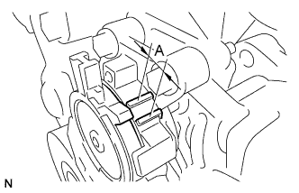
Inspect the V-ribbed belt.
-
Check that the tension indicator is within range A on the auto tensioner scale.
If the tension indicator is not within range A, replace the belt with a new one.
-
-
-
INSPECT ENGINE IDLE SPEED
CAUTION:
-
Turn all the electrical systems and the A/C OFF.
-
Inspect the engine idle speed with the cooling fan stopped.
-
When checking the idle speed, shift the transmission to the neutral position.
-
Warm up and stop the engine.
-
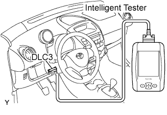
Connect the intelligent tester to the DLC3.
-
Turn the ignition switch on.
-
Select the following items.
Powertrain / Engine / Data List / Engine SPD.
Tech Tips
Refer to the intelligent tester operator's manual if you select Data List.
-
Inspect the engine idle speed.
Idle speed 700 to 800 rpm -
Turn the ignition switch off.
-
Disconnect the intelligent tester from the DLC3.
-
-
INSPECT MAXIMUM ENGINE SPEED
-
Start the engine.
-
Fully depress the accelerator pedal.
-
Check the maximum engine speed.
Maximum engine speed 5100 rpm
-
-
INSPECT COMPRESSION
-
Warm up and stop the engine.
-
Remove the engine cover No.1 Click here.
-
Disconnect the negative battery cable.
-
Disconnect the positive battery cable.
-
Remove the air cleaner cap sub-assembly Click here.
-
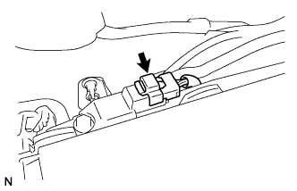
Disconnect the turbo pressure sensor connector.
-
Remove the turbo pressure sensor.
-
Remove the air cleaner case sub-assembly Click here.
-
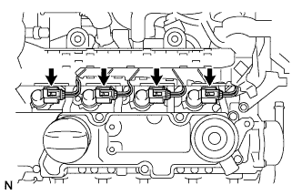
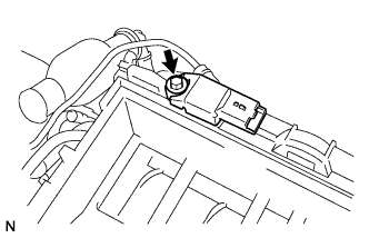
Disconnect the injector connectors.
-
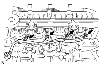
Remove the 4 nuts, and disconnect the glow plug harness.
-
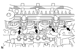
Remove the 4 glow plugs.
-
Install SST into the glow plug hole.
- SST
- 09992-00025 ( 09992-00112, 09992-00211 )
-
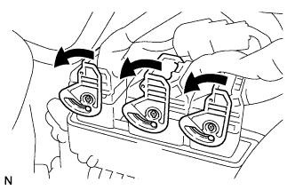
Turn the retainer of the ECM connectors as shown in the illustration.
-
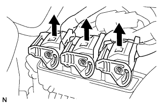
Disconnect the ECM connectors from the ECM.
-
Connect the positive battery cable.
-
Connect the negative battery cable.
-
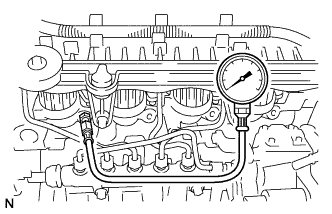
Inspect cylinder compression pressure.
-
While cranking the engine, measure the compression pressure.
Compression pressure 1500 to 2500 kPa (15 to 25 bar, 218 to 363 psi) Difference between each cylinder 500 kPa (5 bar, 73 psi) Note
-
Inspect the other cylinders in the same way.
-
Measure the compression as quickly as possible.
-
-
If the cylinder compression is low, pour a light coat of engine oil into the cylinder through the glow plug holes, then inspect it again.
Tech Tips
-
If adding oil increases the compression, the piston rings and/or cylinder bore may be worm damaged.
-
If pressure stays low, the valve may be stuck or seated improperly, or there leakage from the gasket.
-
-
-
Disconnect the negative battery cable.
-
Disconnect the positive battery cable.
-
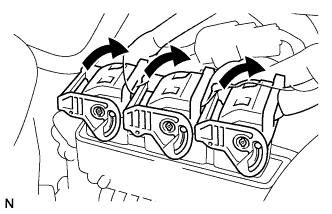
Connect the ECM connectors to the ECM.
-
Turn the retainers as shown in the illustration.
-
Remove the SST.
-
Install the 4 glow plugs.
- Torque:
- 8.5 N*m { 87 kgf*cm, 73 in.*lbf }
-
Connect the glow plug harness.
-
Install the 4 nuts.
- Torque:
- 1.2 N*m { 12 kgf*cm, 11 in.*lbf }
-
Connect the injector connectors.
-
Install the air cleaner case sub-assembly Click here.
-
Install the turbo pressure sensor.
- Torque:
- 4.0 N*m { 41 kgf*cm, 35 in.*lbf }
-
Connect the turbo pressure sensor connector.
-
Install the air cleaner cap sub-assembly Click here.
-
Connect the positive battery cable.
- Torque:
- 5.4 N*m { 55 kgf*cm, 48 in.*lbf }
-
Connect the negative battery cable.
- Torque:
- 5.4 N*m { 55 kgf*cm, 48 in.*lbf }
-
Install the engine cover No.1 Click here.
-