ENGINE UNIT REASSEMBLY

-
INSTALL W/ PIN PISTON SUB-ASSEMBLY
-
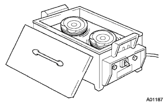
Gradually heat new piston up to 80 to 90°C (176 to 194°F)
-
Apply engine oil to the smaller end of a new connecting rod and new piston pin.
-
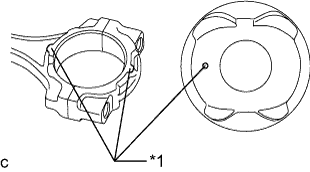
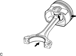
Text in Illustration *1 Front Mark Align the front marks on the piston and connecting rod and assemble them.
-
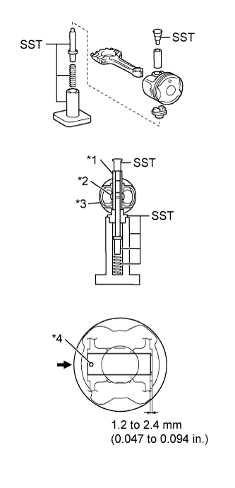
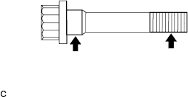
Text in Illustration *1 Piston Pin *2 Connecting Rod *3 Piston *4 Front Mark Using SST and a press, press in the piston pin.
- SST
- 09221-25026 ( 09221-00021, 09221-00030, 09221-00130, 09221-00141, 09221-00150 )
Note
-
Press in the piston pin from the front mark side of the piston.
-
Do not press in the piston pin at an angle.
-
Hold the connecting rod and check that the piston moves slightly.
-
-
INSTALL PISTON RING SET
-
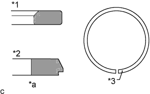
Text in Illustration *1 No. 1 Compression Ring *2 No. 2 Compression Ring *3 Identification Mark *a Cross Section Install new piston rings.
-
Using a piston ring expander, install a new No. 2 compression ring and a new No. 1 compression ring with identification marks (T) facing upward.
-
Text in Illustration *1 No. 1 Compression Ring *2 No. 2 Compression Ring *3 Oil Ring (Side Rail) *4 Oil Ring (Expander) *5 Front Mark Install the rings so that each end facing as shown in the illustration.
-
-
INSTALL CRANKSHAFT BEARING
-
Align the crankshaft lower bearing with the bearing cap and install the crankshaft bearing cap.
Note
-
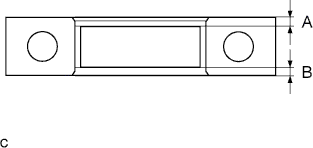
Be sure to install the bearing cap so that the gap between A and B is less than 0.8 mm (0.031 in.).
-
Do not apply engine oil to the bearing and its contact surface.
-
-
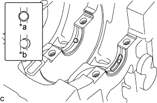
Text in Illustration *a CORRECT *b INCORRECT Align the crankshaft bearing (upper) with the oil hole of the cylinder block and install the bearing.
Note
Do not apply engine oil to the bearing and its contact surface.
-
-
INSTALL CRANKSHAFT
-
Text in Illustration *a Oil Groove Apply engine oil to the oil groove.
-
Install the 2 crankshaft thrust washers onto the No. 3 journal position of the cylinder block with the oil grooves facing outward.
-
Apply engine oil to the sliding surface of the crankshaft bearing (upper) and install the crankshaft.
-
Apply engine oil to the sliding surface of the crankshaft bearing (lower) and install the crankshaft bearing cap with the front mark facing forward.
-
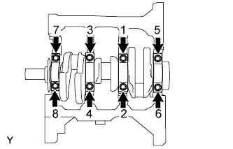
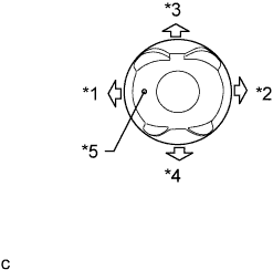
Apply engine oil to the crankshaft bolts and install them in 2 or 3 steps in the order shown in the illustration.
- Torque:
- 59 N*m { 602 kgf*cm, 44 ft.*lbf }
-
Make sure that the crankshaft turns smoothly.
-
-
INSTALL CONNECTING ROD BEARING
-
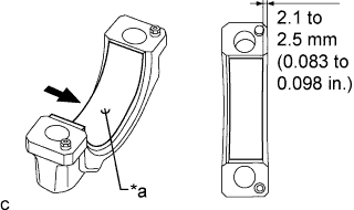
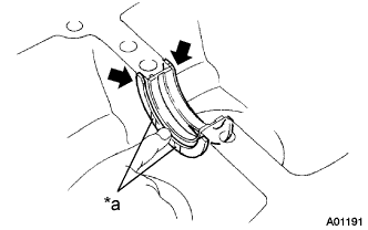
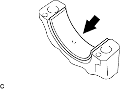
Text in Illustration *a Oil Groove Align the connecting rod bearing oil groove of the connecting rod cap.
-
Install the connecting rod bearing to the connecting rod bearing cap as shown in the illustration.
Note
Do not apply engine oil to the bearing and its contact surface.
-
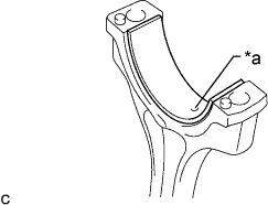
Text in Illustration *a Oil Groove Align the connecting rod bearing oil groove of the connecting rod.
-
Install the connecting rod bearing to the connecting rod.
Note
Do not apply engine oil to the bearing and its contact surface.
-
-
INSTALL CONNECTING ROD SUB-ASSEMBLY
-
Text in Illustration *1 No. 1 Compression Ring *2 No. 2 Compression Ring *3 Oil Ring (Side Rail) *4 Oil Ring (Expander) *5 Front Mark Make sure that the compression rings and oil ring are installed in the correct direction respectively.
-
Apply engine oil to the sliding surfaces of the piston and connecting rod sub-assembly.
-
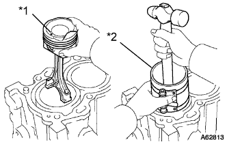
Text in Illustration *1 Front Mark *2 Piston Ring Compressor Using a piston ring compressor, correctly push the numbered piston and connecting rod assemblies into each cylinder with the front mark of the piston facing forward.
-
Apply engine oil to the sliding surface of the connecting rod bearing.
-
Text in Illustration *1 Front Mark Install the connecting rod with the front mark of the connecting rod bearing cap facing forward.
Note
-
Be sure to install the connecting rod bearing cap with the front mark facing forward. Make sure that the knock pin aligns with the knock pin hole.
-
Do not change the connecting rod and connecting rod bearing cap combination.
-
-
Apply a small amount of engine oil to the seating position and threads of the connecting rod bolt.
-
Alternately tighten the connecting rod bolts in 2 or 3 steps.
- Torque:
- 15 N*m { 153 kgf*cm, 11 ft.*lbf }
-
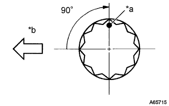
Text in Illustration *a Paint Mark *b Engine Front Mark the front of the connecting cap bolts with paint.
-
Retighten the cap bolts by an additional 90° as shown in the illustration.
-
Check that the crankshaft turns smoothly.
-
-
INSTALL ENGINE REAR OIL SEAL RETAINER
-
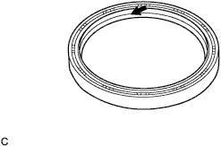
Apply engine oil to the lip of a new oil seal.
-
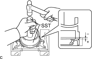
Using SST, tap the oil seal straight in.
Oil seal tap in depth -0.5 to 1.0 mm (0.020 to 0.039 in.) Note
Do not tap the rear engine oil seal at an angle.
- SST
- 09950-60020 ( 09951-00890 )
- 09950-70010 ( 09951-07200 )
-
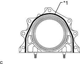
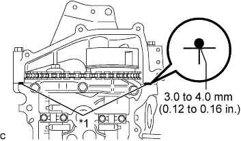
Text in Illustration *1 Seal Packing (Bead Diameter 3.0 to 4.0 mm) Apply a continuous bead of seal packing as shown in the illustration.
Seal packing Toyota Genuine Seal Packing Black, Three Bond 1207B or equivalent Bead diameter 3.0 to 4.0 mm (0.12 to 0.16 in.) Note
Install the cylinder block within 3 minutes after applying seal packing.
-
Install the oil seal retainer with the 5 bolts.
- Torque:
- 10 N*m { 102 kgf*cm, 7 ft.*lbf }
-
-
INSTALL VENTILATION BAFFLE PLATE
-
Clean the installation surface of the cylinder block and ventilation baffle plate.
-
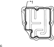
Text in Illustration *1 Seal Packing (Bead Diameter 3.0 to 4.0 mm) Apply a continuous bead of seal packing as shown in the illustration.
Seal packing Toyota Genuine Seal Packing Black, Three Bond 1207B or equivalent Bead diameter 3.0 to 4.0 mm (0.12 to 0.16 in.) Note
Install the cylinder block within 3 minutes after applying seal packing.
-
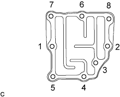
Install the ventilation baffle plate with the 6 bolts and 2 nuts as shown in the illustration.
- Torque:
- 24 N*m { 245 kgf*cm, 18 ft.*lbf }
Note
Install the ventilation baffle plate within 3 minutes after applying seal packing.
-
-
INSTALL CYLINDER BLOCK WATER JACKET SPACER
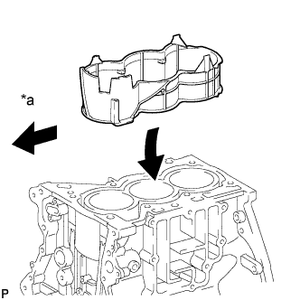
Text in Illustration *a Engine Front
-
Install the cylinder block water jacket spacer to the cylinder block.
-
-
INSTALL VALVE
-
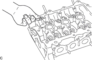
Install the 12 valve spring seats to the cylinder head.
-
Apply a light coat of engine oil to 12 new valve stem oil seals.
-
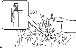
Using SST, push in the valve stem oil seals by hand.
- SST
- 09201-41020
-
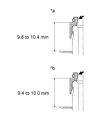
Text in Illustration *a Intake Side *b Exhaust Side Make sure that the valve stem oil seal is pushed in by the specified amount as shown in the illustration.
Standard length Item Specification Intake 9.8 to 10.4 mm (0.386 to 0.409 in.) Exhaust 9.4 to 10.0 mm (0.370 to 0.394 in.) -
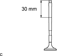
Apply engine oil to each valve area of 30 mm (1.18 in.) or more from its tip as shown in the illustration.
-
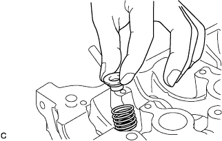
Install the valves, inner compression springs and valve seat retainers onto the cylinder head.
-
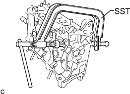
Using SST, compress the inner compression springs and place the 2 valve spring retainer locks around the valve stem.
- SST
- 09202-87002
-
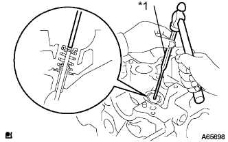
Text in Illustration *1 Pin Punch Using a pin punch, lightly tap the valve stem tip to ensure a proper fit.
Note
Do not damage the valve stem tip.
-
Text in Illustration *a Apply Engine Oil Apply engine oil to the top surfaces of the valve as shown in the illustration.
-
-
INSTALL CYLINDER HEAD SUB-ASSEMBLY
-
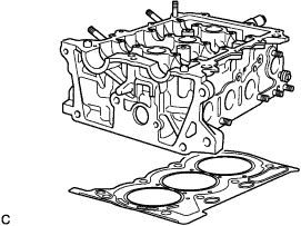
Place a new cylinder head gasket on the cylinder.
Note
Place the cylinder head gently in order not to damage the gasket.
-
Place the cylinder head on the cylinder block.
-
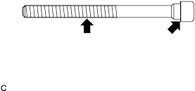
Apply engine oil to each bolt thread and seating surface and install them.
-
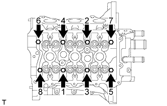
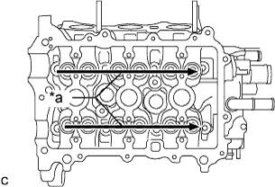
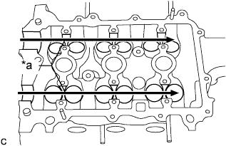
Tighten the bolts in 2 or 3 steps in the order shown in the illustration to install the cylinder head.
-
Tighten the bolts to the specified torque.
- Torque:
- 32 N*m { 326 kgf*cm, 24 ft.*lbf }
-
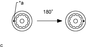
Text in Illustration *a Paint Mark Mark the front of each cylinder head bolt with paint.
-
Retighten the cylinder head bolts by 180° as shown in the illustration.
-
Check that the painted marks are now 180° from the front.
-
-
INSTALL VALVE LIFTER
-
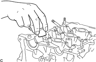
Apply engine oil to the circumference of the valve lifters.
-
Install them straight into the lifter holes.
Note
Check that the valve lifters turn smoothly after installing them.
-
-
INSTALL CAMSHAFTS
-
Before installing the camshaft approximately 90° in the engine revolution direction from the point where the No. 1 piston is set to the TDC so that lifted valve and piston do not contact each other.
-
Text in Illustration *a Apply Engine Oil Apply engine oil to the contact areas of the cam and journal of the No. 1 and No. 2 camshafts.
-
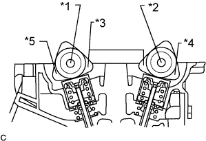
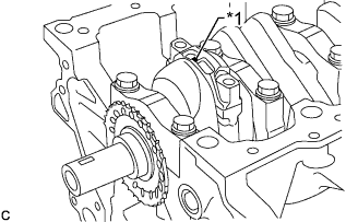
Text in Illustration *1 No. 1 Camshaft *2 No. 2 Camshaft *3 No. 1 Cylinder *4 No. 2 Cylinder *5 No. 3 Cylinder Set the No. 1 camshaft so that the cam noses for the No. 1 and No. 3 cylinders press onto the valve lifters.
-
Set the No. 2 camshaft assembly (on the exhaust side) so that the cam noses for the No. 1 and No. 2 cylinders press onto the valve lifters.
-
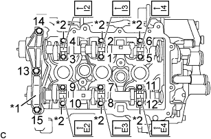
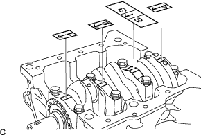
Text in Illustration *1 No. 1 Camshaft Bearing Cap *2 No. 2 Camshaft Bearing Cap Set the camshaft bearing caps No. 1 and No. 2 and tighten the bolts in the order shown in the illustration.
- Torque:
- 15 N*m { 153 kgf*cm, 11 ft.*lbf, for No. 1 Camshaft Bearing Cap }
- 13 N*m { 127 kgf*cm, 9 ft.*lbf, for No. 2 Camshaft Bearing Cap }
Note
-
Be sure to install the bearing caps with the front marks facing engine front.
-
Be sure to install the bolts in each correct position by referring to the inscribed number on the bolts and the table below.
Installation position of the bearing caps No. 2. Installation position Inscribed No. Intake No. 1 cylinder I2 Intake No. 2 cylinder I3 Intake No. 3 cylinder I4 Exhaust No. 1 cylinder E2 Exhaust No. 2 cylinder E3 Exhaust No. 3 cylinder E4
-
-
INSTALL CAMSHAFT TIMING GEAR OR SPROCKET
-
Insert the camshaft timing gear or sprocket so that the knock pin on the No. 2 camshaft end fits into the groove.
-
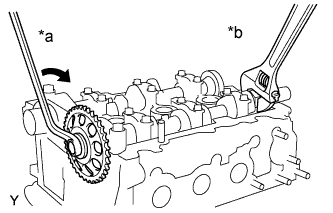
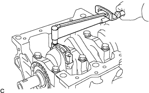
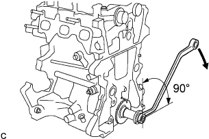
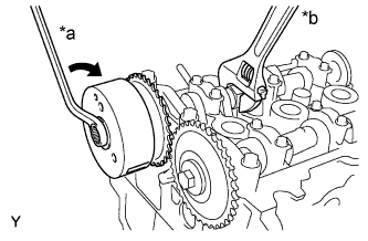
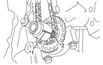
Text in Illustration *a Turn *b Hold While holding the hexagonal portion of the No. 2 camshaft, tighten the bolts to install the camshaft timing gear or sprocket.
- Torque:
- 47 N*m { 479 kgf*cm, 35 ft.*lbf }
-
-
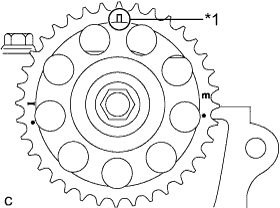
INSTALL CAMSHAFT TIMING SPROCKET ASSEMBLY
-
Apply engine oil to the camshaft timing sprocket installation portion of the camshaft.
-
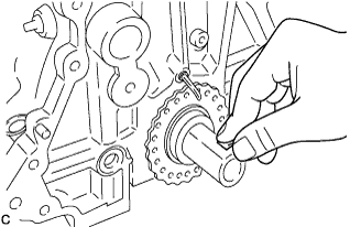
Insert the knock pin on the camshaft end into the knock hole in the camshaft timing sprocket.
Note
-
Slightly turn the sprocket to make sure that the knock pin is securely installed after inserting the knock pin.
-
The end surface of the sprocket may be damaged if the sprocket is turned with excessive force when the knock pin is not inserted.
-
-
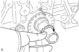
Text in Illustration *a Turn *b Hold While holding the hexagonal portion of the camshaft, tighten the bolts to install the camshaft timing sprocket.
- Torque:
- 47 N*m { 479 kgf*cm, 35 ft.*lbf }
-
-
INSPECT VALVE CLEARANCE
-
INSTALL CRANKSHAFT TIMING GEAR OR SPROCKET
-
Install the key to the crankshaft groove.
-
Install the crankshaft timing sprocket aligning the groove with the key of the crankshaft.
-
-
INSTALL TIMING CHAIN GUIDE
-
Install the timing chain guide with the 2 bolts.
- Torque:
- 9.0 N*m { 92 kgf*cm, 80 in.*lbf }
-
-
INSTALL CHAIN SUB-ASSEMBLY
-
Text in Illustration *1 Timing Mark *2 Yellow Mark Plate Install the timing chain aligning the yellow mark plate with the timing mark of the crankshaft timing sprocket as shown in the illustration.
-
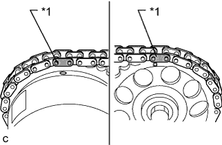
Text in Illustration *1 Orange Mark Plate Install the timing chain aligning the 2 orange mark plates with the timing marks of the camshaft timing sprockets as shown in the illustration.
-
-
INSTALL TIMING CHAIN TENSION ARM
-
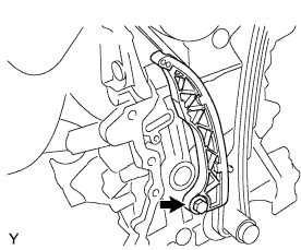
Install the timing chain tension arm with the bolt.
- Torque:
- 19 N*m { 194 kgf*cm, 14 ft.*lbf }
-
-
INSTALL NO. 1 CHAIN TENSIONER ASSEMBLY
-
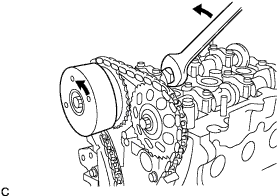
Slightly turn the hexagonal portion of the camshaft (intake side) counterclockwise to leave some slack on the chain of the timing chain tensioner side.
-
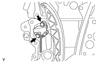
Install the No. 1 chain tensioner with the 2 bolts.
- Torque:
- 11 N*m { 107 kgf*cm, 8 ft.*lbf }
-
Remove the hexagon wrench, turn the crankshaft 2 complete revolutions and operate the chain tension.
-
Text in Illustration *1 Timing Mark Make sure that the timing mark of the sprocket camshaft timing is at the top with the timing chain tensed (set the No. 1 piston to the TDC/exhaust).
-
-
INSTALL TIMING CHAIN COVER OIL SEAL
- SST
- 09608-06041
-
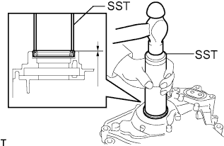
Using SST, tap in a new oil seal until its surface is flush with the timing gear case edge.
Standard distance 0.5 to -1 mm (0.0197 to -0.0394 in.) Note
-
Keep the lip free from foreign matter.
-
Do not tap the oil seal at an angle.
-
-
INSTALL OIL PUMP GASKET
-
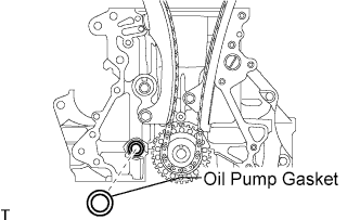
Install a new oil pump gasket.
-
-
INSTALL TIMING CHAIN COVER SUB-ASSEMBLY
-
Apply seal packing in a continuous bead to the engine unit as shown in the following illustration.
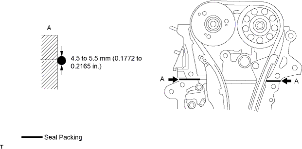
Seal packing Toyota Genuine Seal Packing Black, Three Bond 1207B or equivalent Seal width 4.5 to 5.5 mm (0.1772 to 0.2165 in.) Note
-
When the contact surfaces are wet, wipe off with an oil-free cloth before applying seal packing.
-
Install the crankcase within 3 minutes and tighten the bolts within 15 minutes after applying seal packing.
-
Do not start the engine for at least 2 hours after installing.
-
-
Apply seal packing in a continuous bead to the timing chain cover as shown in the following illustration.
Seal packing Toyota Genuine Seal Packing Black, Three Bond 1207B or equivalent Seal packing Toyota Genuine Seal Packing 1282B, Three Bond 1282B or equivalent Note
-
When the contact surfaces are wet, wipe off with an oil-free cloth before applying seal packing.
-
Install the crankcase within 3 minutes and tighten the bolts within 15 minutes after applying seal packing.
-
Do not start the engine for at least 2 hours after installing.
Tech Tips
Apply seal packing referring to the table and illustration below.
Seal packing diameter Continuous line area 3.0 mm (0.1181 in.) Alternate long and short dashed line area 3.5 to 4.5 mm (0.1378 to 0.1772 in.) Dashed line area 3.0 to 3.5 mm (0.1181 to 0.1378 in.) 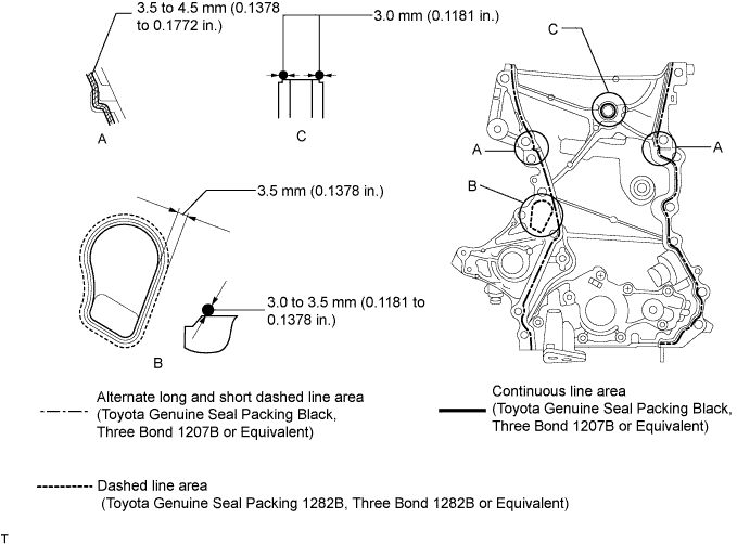
-
-
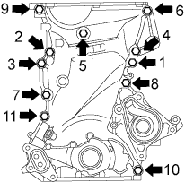
Using several steps, uniformly install and tighten the 11 bolts in the sequence shown in the illustration.
- Torque:
- Bolts 9, 10, and 11
- 24 N*m { 245 kgf*cm, 18 ft.*lbf }
- Bolts except 9, 10, and 11
- 40 N*m { 408 kgf*cm, 30 ft.*lbf }
-
-
INSTALL ENGINE WATER PUMP ASSEMBLY
-
Install the water pump gasket.
-
Temporarily install the engine water pump with the 5 bolts.
-
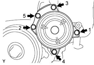
Tighten the 5 bolts in the order shown in the illustration.
- Torque:
- 28 N*m { 286 kgf*cm, 21 ft.*lbf }
-
-
INSTALL CRANKSHAFT PULLEY
-
Align the pulley set key with the key groove of the pulley.
-
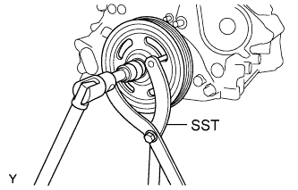
Using SST, hold the pulley in place and tighten the bolt.
- SST
- 09960-10010 ( 09962-01000, 09963-01000 )
- Torque:
- 170 N*m { 1734 kgf*cm, 125 ft.*lbf }
-
-
INSTALL OIL STRAINER SUB-ASSEMBLY
-
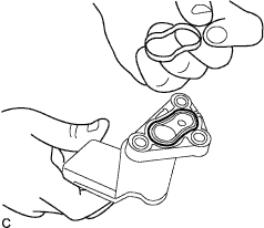
Install a new oil strainer gasket.
-
Install the oil strainer with the 3 bolts.
- Torque:
- 8.5 N*m { 87 kgf*cm, 75 in.*lbf }
-
-
INSTALL OIL PAN SUB-ASSEMBLY
-
Remove any grease from the installation surfaces of the cylinder block and oil pan.
-
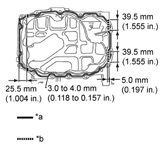
Text in Illustration *a Contact surface between timing chain cover and cylinder block *b Contact surface between oil seal retainer and cylinder block Apply seal packing to the oil pan and install it to the cylinder block.
Seal packing Toyota Genuine Seal Packing Black, Three Bond 1207B or equivalent Note
-
The start and end points of seal packing application must be on the seal surface with the cylinder block.
-
Be sure to apply seal packing to the contact surfaces between the timing chain cover and cylinder block, and between the oil seal retainer and cylinder block.
-
Install the oil pan within 3 minutes and tighten the bolts within 15 minutes after applying seal packing.
-
-
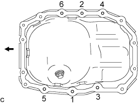
Tighten the specified 6 bolts in the order shown in the illustration.
- Torque:
- 24 N*m { 245 kgf*cm, 18 ft.*lbf }
-
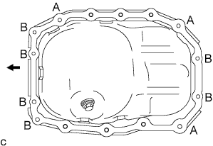
Tighten the 7 bolts and 2 nuts.
- Torque:
- 24 N*m { 245 kgf*cm, 18 ft.*lbf, for A }
- 10 N*m { 102 kgf*cm, 7 ft.*lbf, for B }
-
-
INSTALL OIL FILTER BRACKET
-
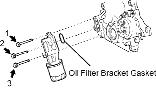
Using several steps, uniformly install and tighten the 3 bolts in the sequence shown in the illustration.
- Torque:
- 24 N*m { 245 kgf*cm, 18 ft.*lbf }
-
-
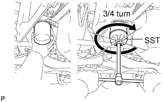
INSTALL OIL FILTER SUB-ASSEMBLY
-
Check and clean the oil filter installation surface.
- SST
- 09228-06501
-
Apply clean engine oil to the gasket of a new oil filter.
-
Lightly screw the oil filter into place, then tighten it until the gasket comes into contact with the seat.
-
Using SST, tighten it an additional 3/4 turn.
-
-
INSTALL CYLINDER HEAD COVER SUB-ASSEMBLY
-
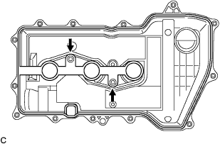
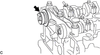
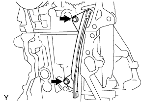
Fit a new cylinder head cover gasket into the groove on the cylinder head cover and onto the center bosses shown by the arrows.
Note
Make sure that the gasket is securely inserted until it completely sits on the roots of the bosses.
-
Text in Illustration *1 Seal Packing Apply seal packing to the upper section of the contact surfaces of the cylinder head and timing chain cover.
Seal packing Toyota Genuine Seal Packing Black, Three Bond 1207B or equivalent Note
Install the cylinder head cover within 3 minutes and tighten the bolts and nuts within 15 minutes after applying seal packing.
-
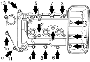
Tighten the 13 bolts and 2 nuts to the specified torque in the order shown in the illustration.
- Torque:
- 7.7 N*m { 79 kgf*cm, 68 in.*lbf }
-
After tightening all of them, make sure that "1" and "2" are tightened with the specified torque.
-