ENGINE UNIT INSPECTION

-
CLEAN TIMING CHAIN OR BELT COVER SUB-ASSEMBLY
-
Clean the timing chain or belt cover sub-assembly Click here.
-
-
CLEAN OIL PAN SUB-ASSEMBLY
-
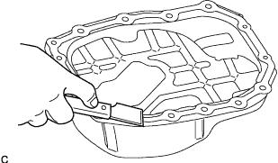
Clean the installation surface of the oil pan sub-assembly.
-
-
INSPECT CHAIN SUB-ASSEMBLY
-
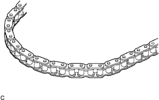
Visually check the timing chain sub-assembly for wear or cracks.
If the timing chain sub-assembly is not normal, replace the timing chain sub-assembly and check the sprocket side too.
-
-
INSPECT CAMSHAFT TIMING GEAR OR SPROCKET
-
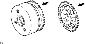
Check the camshaft timing gear or sprocket for wear or damage.
If the camshaft timing gear or sprocket is not normal, replace the camshaft timing gear or sprocket.
-
-
INSPECT CRANKSHAFT TIMING GEAR OR SPROCKET
-
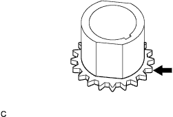
Check the crankshaft timing gear or sprocket for wear or damage.
If the crankshaft timing gear or sprocket is not normal, replace the crankshaft timing gear or sprocket.
-
-
INSPECT TIMING CHAIN GUIDE
-
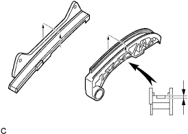
Inspect the wear level of the timing chain guide.
Maximum wear 0.5 mm (0.020 in.) If the wear is greater than the maximum value, replace the timing chain guide.
-
-
INSPECT TIMING CHAIN TENSION ARM
-
Inspect the wear level of the timing chain tension arm.
Maximum wear 0.5 mm (0.020 in.) If the wear is greater than the maximum value, replace the timing chain tension arm.
-
-
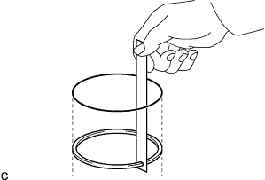
INSPECT CHAIN TENSIONER ASSEMBLY NO.1
-
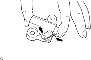
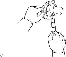
While holding the stopper plate of the chain tensioner assembly No.1 to the left with your fingers, check that the plunger operates smoothly.
-
Release the stopper plate and check that the plunger cannot be pushed with the stopper plate activated.
If the chain tensioner assembly No.1 is not normal, replace the chain tensioner assembly No.1.
-
-
CLEAN CAMSHAFT BEARING CAP
-
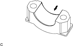
Clean the installation surfaces of the camshaft bearing No.1 and No.2 caps.
-
-
INSPECT CAMSHAFT
-
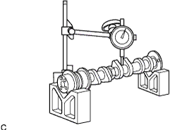
Inspect the camshaft for runout.
-
Using V-blocks and a dial indicator, measure the bend of the third journal.
Maximum circle runout 0.03 mm (0.0012 in.) Tech Tips
The bend is the half of the value on the indicator when the camshaft is turned 1 revolution.
If the circle runout is greater than the maximum value, replace the camshaft.
-
-
Inspect the cam lobes.
-
Using a micrometer, measure the cam lobe height.
Standard cam lobe height 41.54 to 41.64 mm (1.6354 to 1.6394 in.) for intake 40.97 to 41.07 mm (1.6130 to 1.6169 in.) for exhaust Minimum cam lobe height 41.44 mm (1.6315 in.) for intake 40.87 mm (1.6091 in.) for exhaust If the cam lobe height is less than the minimum value, replace the camshaft.
-
-
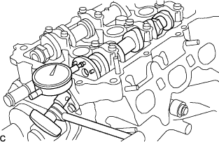
Inspect the camshaft thrust clearance.
-
Install the 2 camshafts.
-
Using dial indicator, measure the thrust clearance while moving the camshaft back and forth.
Standard thrust clearance 0.100 to 0.225 mm (0.00394 to 0.00886 in.) Maximum thrust clearance 0.240 mm (0.00944 in.) If the thrust clearance is greater than maximum, replace the cylinder head. If damages are found on the camshaft thrust surfaces, replace the camshaft.
-
-
-
INSPECT CAMSHAFT OIL CLEARANCE
Note
Do not turn the camshaft.
-
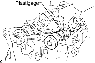
Clean the 7 bearing caps and camshaft journals.
-
Place the camshafts on the cylinder head.
-
Lay a strip of Plastigage on the journal in the axial direction.
-
Confirm the front marks of the camshaft bearing No.1 and No.2 caps and journal number.
-
Tighten the 15 bolts to the specified torque.
- Torque:
- Camshaft bearing cap No.1
- 15 N*m { 153 kgf*cm, 11 ft.*lbf }
- Camshaft bearing cap No.2
- 12.5 N*m { 128 kgf*cm, 9 ft.*lbf }
-
Remove the 7 bearing caps.
-

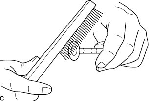
Measure the Plastigage at its widest point.
Standard oil clearance Item Specification Camshaft bearing No.1 for intake 0.025 to 0.061 mm (0.00098 to 0.00240 in.) Camshaft bearing No.1 for exhaust 0.037 to 0.073 mm (0.00146 to 0.00287 in.) Camshaft bearing No.2 for intake 0.035 to 0.072 mm (0.00138 to 0.00283 in.) Camshaft bearing No.2 for exhaust 0.035 to 0.072 mm (0.00138 to 0.00283 in.)
-
-
INSPECT CAMSHAFT TIMING GEAR ASSEMBLY
-
Inspect the camshaft timing gear assembly Click here.
-
-
CLEAN VALVE
-
Remove all carbon on the valves.
CAUTION:
Be sure to wear protective goggles while servicing.
-
-
INSPECT INNER COMPRESSION SPRING
-
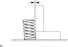
Using a straight edge and feeler gauge, measure the deviation of the inner compression spring.
Maximum deviation 1.5 mm (0.059 in.) If the deviation is greater than the maximum value, replace the inner compression spring.
-
-
INSPECT VALVE SEATS
-
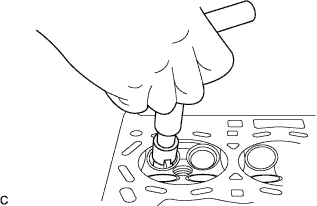
Apply a light coat of prussian blue (or white lead) to the valve face.
-
Lightly press the valve against the seat.
Note
Do not rotate the valve.
-
Check the valve face and seat according to the following procedure.
-
If blue appears 360 degrees around the face, the valve is concentric. If not, replace the valve.
-
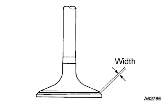
If blue appears 360 degrees around the valve seat, the guide and face are concentric. If not, resurface the seat.
Standard width Item Specification Intake 1.20 to 1.70 mm (0.0472 to 0.0669 in.) Exhaust 1.11 to 1.61 mm (0.0437 to 0.0634 in.)
-
-
-
REPAIR VALVE SEATS
-
Using a 45 degrees cutter, resurface the valve seat so that the valve seat width is more than the specification.
Note
-
Repair the seat while checking the seating position.
-
Gradually reduce the force in order to prevent joggling on the resurfaced face.
-
-
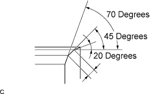
Check each valve setting position. Using 45 degrees cutter, resurface the valve seat so that the valve seat contacts in the middle of the valve face.
-
Using 20 degrees and 70 degrees cutters, resurface the valve seat so that the valve seat contacts around the entire valve seat and the valve seat width is the specification.
-
Handrub the valve and valve seat with an abrasive compound.
-
-
INSPECT CYLINDER HEAD BOLT
-
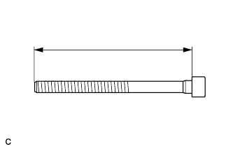
Using a vernier caliper, measure the cylinder head bolt length.
Maximum length 123.5 mm (4.862 in.) If the overall length is greater than the maximum value, replace the cylinder head bolt.
-
-
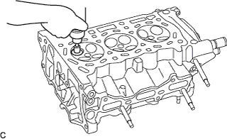
CLEAN CYLINDER BLOCK SUB-ASSEMBLY
-
Using an oil stone or similar device, clean the chain cover surface, cylinder head surface, oil pan sub-assembly surface, and ventilation baffle plate surface of the cylinder block.
CAUTION:
Be sure to wear protective goggles while servicing.
Note
-
Do not damage the cylinder block sub-assembly while servicing.
-
Do not drop any cylinder head gasket material into the water jacket.
-
-
-
CLEAN PISTON
-
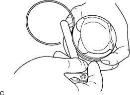
Using an old piston ring or similar device, remove all carbon on each piston.
CAUTION:
Be sure to wear protective goggles while servicing.
Note
Do not damage the piston while servicing.
-
Clean off all the carbon on each part using solvent.
-
-
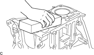
INSPECT CYLINDER BLOCK SUB-ASSEMBLY
-
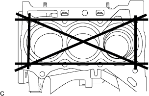
Using a straight edge and feeler gauge, measure warpage on the contact surface indicated in the illustration.
Maximum warpage 0.05 mm (0.0020 in.) If the warpage is greater than the maximum value, replace the cylinder block sub-assembly.
-
-
INSPECT CYLINDER BORE
-
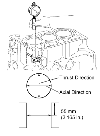
Using a cylinder gauge, measure the cylinder bore diameter in the thrust and axial directions at the position shown in the illustration.
Standard diameter 71.000 to 71.013 mm (2.79527 to 2.79578 in.) Maximum diameter 71.133 mm (2.80051 in.) If the cylinder bore diameter is greater than the maximum, replace the cylinder block.
-
-
INSPECT PISTON
-
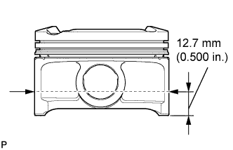
Measure the outer diameter of the piston in a vertical direction to the pin hole at the point 12.7 mm (0.500 in.) away from the bottom end of the skit.
Piston diameter 70.945 to 70.963 mm (2.79311 to 2.79381 in.) Minimum diameter 70.945 mm (2.79311 in.) If the diameter is not as specified, replace the piston.
-
-
INSPECT PISTON OIL CLEARANCE
-
Subtract the piston diameter measurement from the cylinder bore diameter measurement.
Clearance Standard oil clearance 0.037 to 0.068 mm (0.00146 to 0.00268 in.) Maximum oil clearance 0.098 mm (0.00386 in.)
-
If the oil clearance is greater than the maximum value, replace all of the piston assembly.
-
If necessary, replace the cylinder block.
Tech Tips
-
The oil clearance of the piston and cylinder block can be calculated by subtracting the cylinder inner diameter in the thrust direction from the piston outer diameter.
-
Be sure to perform the measurement at the point with the most wear because there is joggling wear on the upper end of the piston ring sliding area.
-
-
-
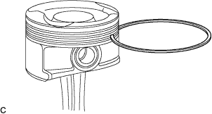
INSPECT PISTON GROOVE CLEARANCE
-
Using a feeler gauge, measure the clearance between the new piston ring and wall of the ring groove.
Standard ring groove clearance Item Specified No.1 ring 0.02 to 0.07 mm (0.0008 to 0.0028 in.) No.2 ring 0.02 to 0.06 mm (0.0008 to 0.0024 in.) Oil ring 0.020 to 0.065 mm (0.00079 to 0.00256 in.) If the ring groove clearance is not as specified, replace the piston assembly.
-
-
INSPECT PISTON RING END GAP
-
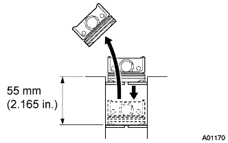
Using a piston, push the piston ring a little beyond the bottom of the ring travel, which is 55 mm (2.165 in.) from the top of the cylinder block sub-assembly.
-
Using a feeler gauge, measure the end gap.
Standard end gap Item Specification No.1 ring 0.20 to 0.30 mm (0.0079 to 0.0118 in.) No.2 ring 0.40 to 0.60 mm (0.0157 to 0.0236 in.) Oil ring 0.10 to 0.40 mm (0.0039 to 0.0157 in.) Maximum end gap Item Specification No.1 ring 0.79 mm (0.0311 in.) No.2 ring 0.75 mm (0.0295 in.) Oil ring 0.69 mm (0.0272 in.)
-
If the end gap is greater than the maximum value, replace the piston ring.
-
If the end gap is greater than the maximum value, even with a new piston ring, replace the cylinder block sub-assembly.
-
-
-
INSPECT CRANKSHAFT
-
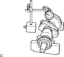
Using a dial indicator and V-blocks, measure the circle runout as shown in the illustration.
Standard circle runout 0.03 mm (0.0012 in.) Maximum circle runout 0.04 mm (0.0016 in.) If the circle runout is greater than the maximum value, replace the crankshaft.
Tech Tips
The bend is the half of the value on the indicator when the crankshaft is turned 1 revolution.
-
Using a micrometer, measure the diameter of each main journal at the points shown in the illustration.
Diameter 43.988 to 44.000 mm (1.73181 to 1.73228 in.) If the diameter is not as specified, check the crankshaft oil clearance.
-
Check each main journal for elliptic degree and tapered amount as shown.
Maximum elliptic degree and tapered amount 0.03 mm (0.0012 in.) If the the elliptic degree or tapered amount is greater than the maximum value, replace the crankshaft.
Tech Tips
-
Elliptic degree : A - B or a - b
-
Tapered amount : A - a or B - b
-
-
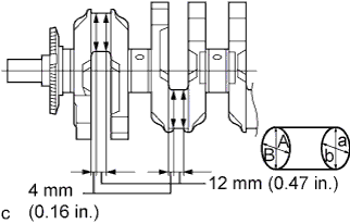
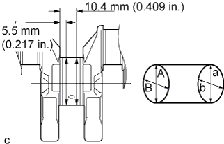
Using a micrometer, measure the diameter of each crankshaft pin at the points shown in the illustration.
Diameter 39.992 to 40.000 mm (1.57449 to 1.57480 in.) If the diameter is not as specified, check the connecting rod oil clearance.
-
Check each crankshaft pin for elliptic degree and tapered amount as shown.
Maximum elliptic degree and tapered amount 0.03 mm (0.0012 in.) If the the elliptic degree or tapered amount is greater than the maximum value, replace the crankshaft.
Tech Tips
-
Elliptic degree : A - B or a - b
-
Tapered amount : A - a or B - b
-
-
-
INSPECT CONNECTING ROD SUB-ASSEMBLY
-
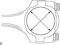
Using a cylinder gauge, measure the connecting rod sub-assembly big end diameter as shown in the illustration.
Standard diameter Mark Specification 1 43.000 to 43.008 mm (1.69291 to 1.69323 in.) 2 43.009 to 43.016 mm (1.69326 to 1.69354 in.) 3 43.017 to 43.024 mm (1.69358 to 1.69386 in.) If the diameter is not specified, replace the connecting rod sub-assembly.
-
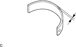
Using a micrometer, measure the thickness of the connecting rod bearing.
Standard thickness 1.492 to 1.501 mm (0.05874 to 0.05909 in.) If the thickness is not as specified, replace the connecting rod bearing.
-
-
INSPECT CONNECTING ROD BOLT
-
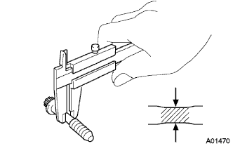
Using vernier calipers, measure the tension portion diameter of the bolts.
Minimum diameter 6.4 mm (0.252 in.) If the diameter is less than the minimum value, replace the connecting rod bolt.
-