ENGINE UNIT DISASSEMBLY

-
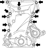
REMOVE CYLINDER HEAD COVER SUB-ASSEMBLY
-

Remove the 13 bolts and 2 nuts in the order shown in the illustration.
-
Remove the cylinder head cover gasket from the cylinder head cover.
-
-
REMOVE OIL FILTER SUB-ASSEMBLY
-
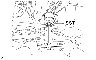
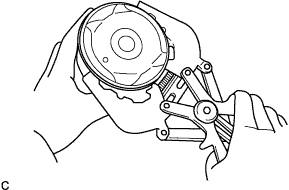
Using SST, remove the oil filter.
- SST
- 09228-06501
-
-
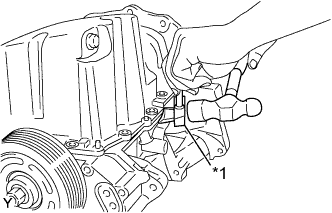
REMOVE OIL FILTER BRACKET
-
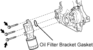
Remove the 3 bolts, oil filter bracket and oil filter bracket gasket.
-
-
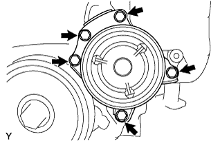
REMOVE ENGINE WATER PUMP ASSEMBLY
-
Remove the 5 bolts and the engine water pump.
-
Remove the water pump gasket.
-
-
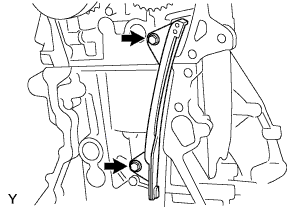
SET NO. 1 CYLINDER TO TDC/EXHAUST
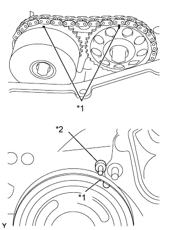
Text in Illustration *1 Timing Mark *2 Timing Pointer
-
Turn the crankshaft pulley clockwise to align the timing mark (0°) of the pulley with the timing pointer of the timing chain cover.
-
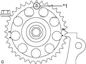
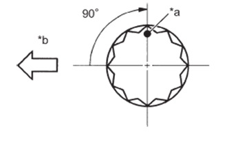
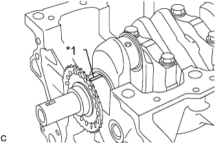
Text in Illustration *1 Timing Mark Check that the timing mark of the camshaft timing sprocket is at the top as shown in the illustration.
Tech Tips
If not, turn the crankshaft pulley 1 complete revolution (360°) so that the timing mark comes to the top.
-
-
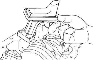
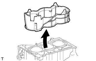
REMOVE OIL PAN SUB-ASSEMBLY
-
Remove the 13 bolts and 2 nuts.
-
Text in Illustration *1 Oil Pan Seal Cutter Using an oil pan seal cutter, remove the oil pan.
Note
Do not damage the flange of the oil pan.
-
-
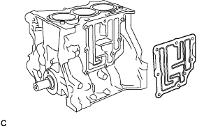
REMOVE OIL STRAINER SUB-ASSEMBLY
-
Remove the 3 bolts and the oil strainer.
-
Remove the oil strainer gasket.
-
-
REMOVE CRANKSHAFT PULLEY
-
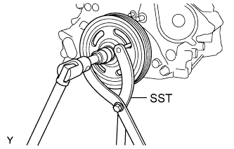
Using SST, hold the crankshaft pulley and loosen the pulley bolt.
- SST
- 09960-10010 ( 09962-01000, 09963-01000 )
-
Remove the crankshaft pulley.
-
-
REMOVE TIMING CHAIN COVER SUB-ASSEMBLY
-
Remove the 11 bolts.
-
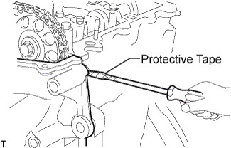
Remove the timing chain or belt cover by prying between the timing chain or belt cover and cylinder head or cylinder block with a screwdriver.
Note
Be careful not to damage the contact surfaces of the cylinder head, cylinder block and timing chain cover.
Tech Tips
Tape the screwdriver tip before use.
-
-
REMOVE OIL PUMP GASKET
-
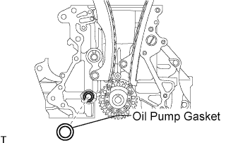
Remove the oil pump gasket.
-
-
REMOVE TIMING CHAIN COVER OIL SEAL
-
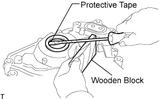
Using a screwdriver with its tip taped, pry out the oil seal.
Tech Tips
Tape the screwdriver tip before use.
-
-
REMOVE NO. 1 CHAIN TENSIONER ASSEMBLY
-
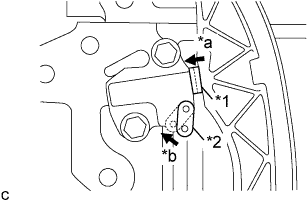
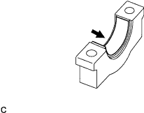
Text in Illustration *1 Plunger *2 Stopper Plate *a Push *b Released Turn the stopper plate of the chain tensioner chain clockwise and push in the plunger with the lock released.
-
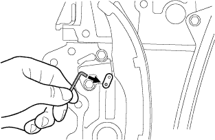
Insert a hexagon wrench into the hole on the stopper plate to lock with the plunger pushed in.
-
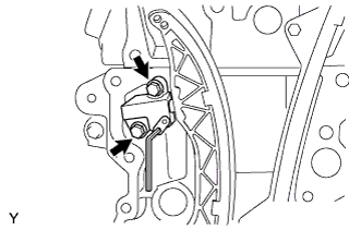
Remove the 2 bolts and the chain tensioner.
-
-
REMOVE TIMING CHAIN TENSION ARM
-
Remove the bolt and the timing tension arm.
-
-
REMOVE CHAIN SUB-ASSEMBLY
-
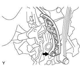
REMOVE TIMING CHAIN GUIDE
-
Remove the 2 bolts and the timing chain guide.
-
-
REMOVE CRANKSHAFT TIMING GEAR OR SPROCKET
-
Remove the crankshaft timing gear or sprocket.
-
Remove the key.
-
-
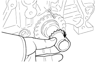
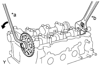
REMOVE CAMSHAFT TIMING SPROCKET ASSEMBLY

Text in Illustration *a Turn *b Hold
-
Remove the bolt from the camshaft timing sprocket while holding the hexagonal portion of the camshaft.
-
Remove the camshaft timing sprocket from the camshaft.
-
-
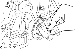
REMOVE CAMSHAFT TIMING GEAR OR SPROCKET
Text in Illustration *a Turn *b Hold
-
Remove the bolt from the camshaft timing gear or sprocket while holding the hexagonal portion of the camshaft.
-
Remove the camshaft timing gear or sprocket from the No. 2 camshaft.
-
-
REMOVE CAMSHAFTS
-
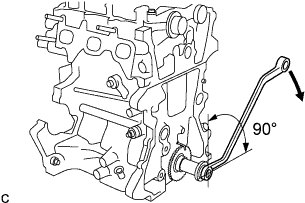
Temporarily tighten the bolt of the crankshaft.
-
Turn the crankshaft by approximately 90° in the engine revolution direction at the point where the No. 1 piston is set to the TDC/exhaust so that the lifted valve and piston do not contact each other when removing the camshaft.
-
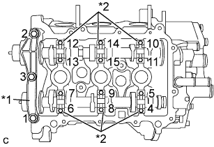
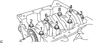
Text in Illustration *1 No. 1 Camshaft Bearing Cap *2 No. 2 Camshaft Bearing Cap Remove the 15 bolts in the order shown in the illustration.
-
Remove the camshaft bearing caps No. 1 and No. 2.
-
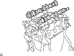
Remove the camshafts No. 1 and No. 2.
-
-
REMOVE VALVE LIFTER
-
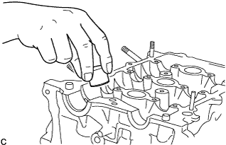
Remove the 12 valve lifters.
Note
-
Record each inscribed mark on the valve lifters for each valve after removing them.
-
Arrange the valve lifters for each cylinder.
-
-
-
REMOVE CYLINDER HEAD SUB-ASSEMBLY
-
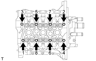
Using several steps, uniformly loosen and remove the 8 cylinder head bolts in the order shown in the illustration.
-
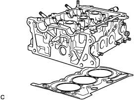
Remove the cylinder head and cylinder head gasket from the cylinder block.
-
-
REMOVE VALVE
-

Using SST, remove the intake and exhaust valve spring retainer locks, valve retainer springs, and compression springs.
- SST
- 09202-87002 ( 09202-00010 )
Note
Arrange the removed parts for each cylinder.
-
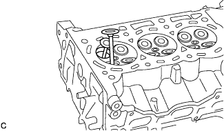
Remove the intake and exhaust valves.
Note
Arrange the valves for each cylinder.
-
Text in Illustration *1 Needle-nose Pliers Using needle-nose pliers, remove the valve stem oil seals.
-
Remove the valve spring seats.
-
-
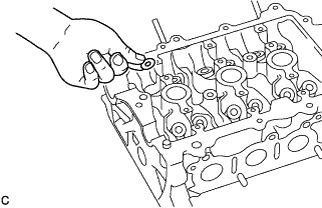
CLEAN CYLINDER HEAD SUB-ASSEMBLY
-
Using a scraper, clean the cylinder block surface and manifold of the cylinder head.
CAUTION:
-
Be sure to wear protective goggles while servicing.
-
Do not damage the cylinder head.
-
Do not drop cylinder head gasket material into the water jacket.
-
-
-
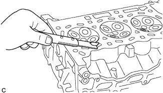
INSPECT CYLINDER HEAD SUB-ASSEMBLY
-
Using a straightedge and feeler gauge, measure warpage on the contact surface indicated in the illustration below.
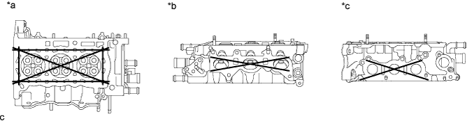
Text in Illustration *a Cylinder Block Side *b Intake Side *c Exhaust Side - - Maximum warpage 0.05 mm (0.0020 in.) If the warpage is greater than the maximum value, replace the cylinder head sub-assembly.
-
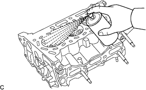
Using a dye penetrant, check the combustion chamber, intake ports, exhaust ports and cylinder block surface for cracks.
-
-
REMOVE CYLINDER BLOCK WATER JACKET SPACER
-
Remove the cylinder block water jacket spacer.
-
-
REMOVE VENTILATION BAFFLE PLATE
-
Remove the 6 bolts, 2 nuts and the ventilation baffle plate.
-
-
REMOVE ENGINE REAR OIL SEAL RETAINER
-
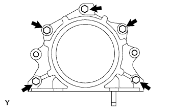
Remove the 5 bolts and the engine rear oil seal retainer.
-
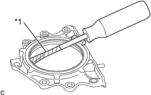
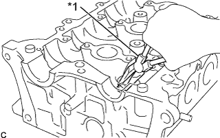
Text in Illustration *1 Protective Tape Using a screwdriver, remove the engine rear oil seal.
Tech Tips
Tape the screwdriver tip before use.
-
-
INSPECT CONNECTING ROD THRUST CLEARANCE
-
Using a feeler gauge, measure the thrust clearance of the connecting rod.
Clearance Standard thrust 0.1 to 0.3 mm (0.004 to 0.012 in.) Maximum thrust 0.35 mm (0.0138 in.)
-
-
INSPECT CONNECTING ROD OIL CLEARANCE
-
Remove the 2 bolts, connecting rod bearing cap and connecting rod bearing.
Note
Arrange the removed parts for each cylinder.
-
Clean the connecting rod bearing and crank pin.
-
Text in Illustration *1 Plastigage Lay a strip of Plastigage across the crank pin.
-
Apply a light coat of engine oil to the threads and under the heads of the 2 bolts.
-
Tighten the 2 bolts in several passes to the specified torque.
- Torque:
- 15 N*m { 153 kgf*cm, 11 ft.*lbf }
Note
Do not turn the crankshaft.
-
Text in Illustration *a Paint Mark *b Engine Front Mark the front of the 2 bolts with paint.
-
Retighten the 2 bolts by an additional 90° as shown in the illustration.
-
Remove the 2 bolts, then remove the connecting rod bearing cap and connecting rod bearing.
-
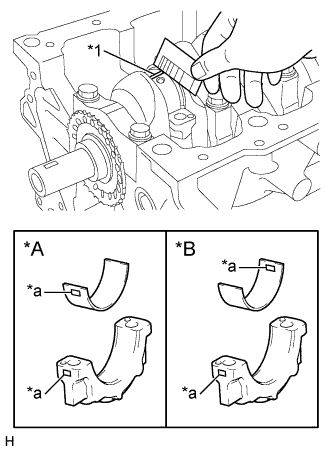
Text in Illustration *A Type A *B Type B *1 Plastigage *a Mark Measure the Plastigage at its widest point.
Standard oil clearance 0.010 to 0.036 mm (0.00039 to 0.00142 in.) Maximum oil clearance 0.036 mm (0.00142 in.)
-
If the oil clearance is greater than the maximum, replace the connecting rod bearings. If necessary, inspect the crankshaft.
-
If replacing a bearing, replace it with one that has the same number as its respective connecting rod cap. Each bearing's standard thickness is indicated by mark 1, 2, or 3 on its surface.
Standard Connecting Rod Bearing Cap Bore Diameter Mark Specified Condition 1 43.000 to 43.008 mm (1.69291 to 1.69323 in.) 2 43.008 to 43.016 mm (1.69323 to 1.69355 in.) 3 43.016 to 43.024 mm (1.69355 to 1.69385 in.) Standard Connecting Rod Bearing Thickness Mark Specified Condition 1 1.492 to 1.495 mm (0.05874 to 0.05886 in.) 2 1.495 to 1.498 mm (0.05886 to 0.05898 in.) 3 1.498 to 1.501 mm (0.05898 to 0.05909 in.) Standard Crankshaft Pin Diameter Mark Specified Condition 1, 2, 3 39.992 to 40.000 mm (1.57445 to 1.57480 in.) Note
Completely remove the Plastigage after the measurement.
Tech Tips
For measuring points of the connecting rod bearing cap bore diameter and connecting rod bearing thickness Click here.
-
-
Perform the measurement for the other connecting rod oil clearance using the same procedure.
-
-
REMOVE CONNECTING ROD SUB-ASSEMBLY
-
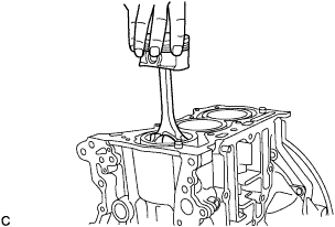
Push the piston, connecting rod and upper bearing through the top of the cylinder block.
Tech Tips
-
Keep the bearing, connecting rod and cap together.
-
Arrange the piston and connecting rod for each cylinder.
-
-
-
INSPECT CRANKSHAFT THRUST CLEARANCE
-
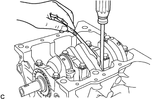
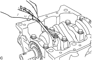
Using a feeler gauge, measure the thrust clearance while prying the crankshaft back and forth with a screwdriver.
Clearance Standard thrust clearance 0.02 to 0.04 mm (0.0008 to 0.0016 in.) Maximum thrust clearance 0.30 mm (0.0118 in.) Tech Tips
-
If the thrust clearance is greater than the maximum value, replace the thrust washer.
-
If the clearance is still greater than the maximum value even after the thrust washer is replaced, replace the crankshaft.
-
-
-
INSPECT CRANKSHAFT OIL CLEARANCE
-
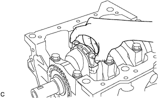
Loosen the 8 bolts in 2 or 3 steps and in the order shown in the illustration.
-
Remove the 8 bolts and the 4 crankshaft bearing caps.
Note
Arrange the removed parts in the removed order.
Tech Tips
-
If it is difficult to remove the crankshaft bearing cap, lightly tap it with a hammer.
-
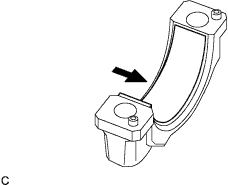
Move the top of the crankshaft bearing cap back and forth in the axial direction.
-
-
Clean the inner surfaces of the crankshaft bearing and crankshaft bearing cap and the journals of the cylinder block and crankshaft.
-
Check these parts for excessive wear and damage.
-
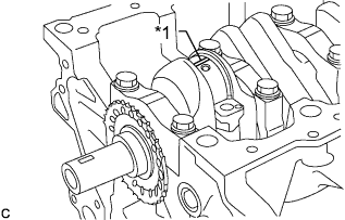
Text in Illustration *1 Plastigage Lay a strip of Plastigage in the axial direction of the crankshaft journal.
-
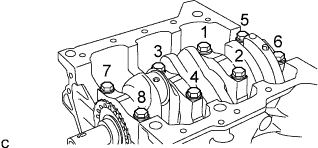
Tighten the 8 bolts in 2 or 3 steps and in the order shown in the illustration.
- Torque:
- 59 N*m { 602 kgf*cm, 44 ft.*lbf }
Note
Do not turn the crankshaft.
-
Remove the 2 bolts, then remove the crankshaft bearing cap and crankshaft bearing.
-
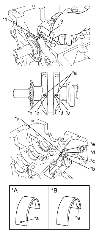
Text in Illustration *A Type A *B Type B *1 Plastigage *a Mark *b No. 1 *c No. 2 *d No. 3 *e No. 4 Measure the Plastigage at its widest point.
Standard oil clearance 0.006 to 0.024 mm (0.00024 to 0.00094 in.) Maximum oil clearance 0.024 mm (0.00094 in.)
-
If the oil clearance is greater than the maximum, replace the crankshaft bearing. If necessary, replace the crankshaft.
-
If replacing a bearing, select a new one with the same number. If the number of the bearing cannot be determined, calculate the correct bearing number by adding together the numbers imprinted on the cylinder block and crankshaft. Then select a new bearing with the calculated number according to the chart below. There are 4 sizes of standard bearings, marked "2", "3", "4" and "5" accordingly.
-
EXAMPLE: Cylinder block mark "2" + Crankshaft mark "2" = Use bearing mark "4"
Standard Cylinder Block Journal Bore Diameter Mark Specified Condition 1 48.000 to 48.006 (1.88976 to 1.89000) 2 48.006 to 48.012 (1.89000 to 1.89023) 3 48.012 to 48.018 (1.89023 to 1.890047) Standard Crankshaft Journal Diameter Mark Specified Condition 1 43.994 to 44.000 (1.73204 to 1.73228) 2 43.988 to 43.994 (1.73171 to 1.73204) Standard Bearing Center Wall Thickness Mark Specified Condition 2 1.994 to 1.997 (0.07850 to 0.07862) 3 1.997 to 2.000 (0.07862 to 0.07874) 4 2.000 to 2.003 (0.07874 to 0.07886) 5 2.003 to 2.006 (0.07886 to 0.07898) Note
Completely remove the Plastigage after the measurement.
-
-
-
REMOVE PISTON RING SET
-
Using a piston ring expander, remove the No. 1 compression ring, No. 2 compression ring and oil ring.
Note
Do not reuse any piston rings.
-
-
REMOVE W/ PIN PISTON SUB-ASSEMBLY
-
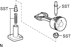
Using SST, press out the piston pin from the piston. Remove the piston.
- SST
- 09221-25026 ( 09221-00021, 09221-00030, 09221-00130, 09221-00141, 09221-00150 )
Tech Tips
-
The piston and pin are a matched set.
-
Arrange the pistons, pins, rings, connecting rods and bearings in correct order.
-