ENGINE ASSEMBLY INSTALLATION

-
INSTALL ENGINE COOLANT TEMPERATURE SENSOR
-
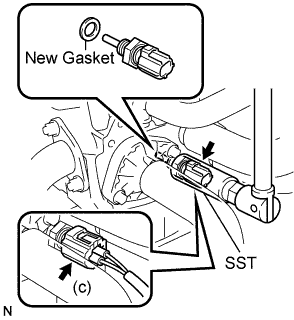
Install a new gasket onto the engine coolant temperature sensor.
- Torque:
- 20 N*m { 200 kgf*cm, 14 ft.*lbf }
-
Using SST, install the engine coolant temperature sensor.
- SST
- 09817-33190
-
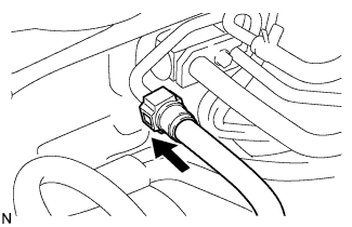
Connect the engine coolant temperature sensor connector.
-
-
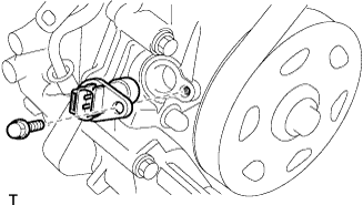
INSTALL CAMSHAFT POSITION SENSOR
-
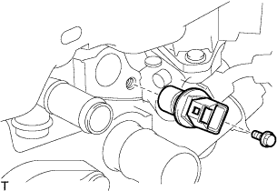
Apply a light coat of engine oil to the O-ring on the sensor.
-
Install the sensor with the bolt.
- Torque:
- 7.5 N*m { 76 kgf*cm, 66 in.*lbf }
-
-
INSTALL KNOCK SENSOR
-
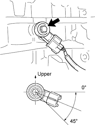
Install the knock control sensor with the bolt.
- Torque:
- 20 N*m { 204 kgf*cm, 15 ft.*lbf }
Tech Tips
It is acceptable for the sensor to be tilted 0° to 45°.
-
Connect the knock control sensor connector.
-
-
INSTALL ENGINE OIL PRESSURE SWITCH ASSEMBLY
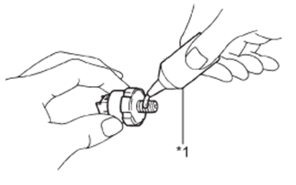
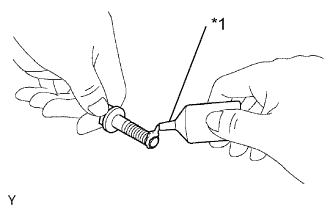
Text in Illustration *1 Adhesive
-
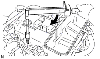
Apply adhesive to 2 or 3 threads of the oil pressure switch assembly.
Adhesive Toyota Genuine Adhesive 1324, Three Bond 1324 or equivalent -
Using a 24 mm deep socket wrench, install the engine oil pressure switch assembly.
- Torque:
- 15 N*m { 153 kgf*cm, 11 ft.*lbf }
-
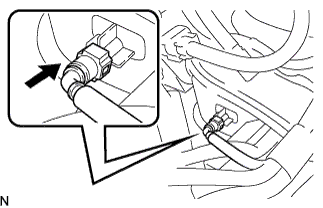
Connect the engine oil pressure switch connector.
-
-
INSTALL OIL CONTROL VALVE FILTER
-
Install the oil control valve filter onto the tight plug.
-
Using an 8 mm socket hexagon wrench, install a new gasket and oil control valve filter.
- Torque:
- 25 N*m { 250 kgf*cm, 18 ft.*lbf }
-
-
INSTALL CAMSHAFT TIMING OIL CONTROL VALVE ASSEMBLY
-
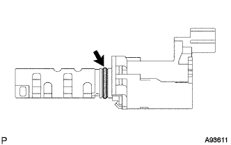
Apply a light coat of fresh engine oil to the O-ring.
-
Install the camshaft timing oil control valve with the bolt.
- Torque:
- 10 N*m { 102 kgf*cm, 7 ft.*lbf }
Note
Do to twist the O-ring.
-
Connect the camshaft timing oil control valve connector.
-
-
INSTALL CRANKSHAFT POSITION SENSOR
-
Apply a light coat of engine oil to the O-ring on the sensor.
-
Install the sensor with the bolt.
- Torque:
- 7.5 N*m { 76 kgf*cm, 66 in.*lbf }
-
-
INSTALL THERMOSTAT
Note
Do not use the dropped water inlet.
-
Install a new thermostat gasket to the thermostat.
-
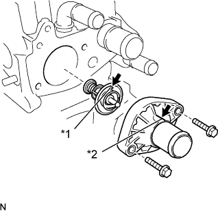
Text in Illustration *1 Jiggle Valve *2 Top Protrusion Install the thermostat with the jiggle valve upward.
Note
Make sure that the jiggle valve is aligned with the top protrusion of the water inlet.
-
Install the water inlet with the 2 bolts.
- Torque:
- 7.0 N*m { 71 kgf*cm, 62 in.*lbf }
Note
Make sure that the thermostat gasket does not get caught between the parts after installing the water inlet.
-
-
INSTALL INTAKE MANIFOLD
-
Install a new intake manifold gasket to the intake manifold.
-
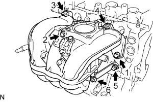
Temporarily install the intake manifold and intake manifold stay with the 4 bolts and 2 nuts.
-
Tighten the 4 bolts and 2 nuts in the order shown in the illustration.
- Torque:
- 30 N*m { 306 kgf*cm, 22 ft.*lbf }
-
Connect the PCV hose.
-
-
INSTALL VACUUM SENSOR
-
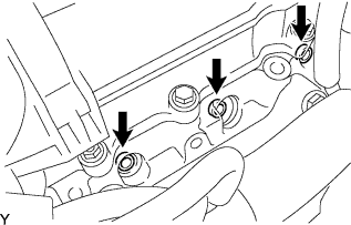
Install the vacuum sensor with the 2 bolts.
- Torque:
- 5.0 N*m { 51 kgf*cm, 44 in.*lbf }
-
Connect the vacuum sensor connector.
-
-
INSTALL FUEL INJECTOR ASSEMBLY
-
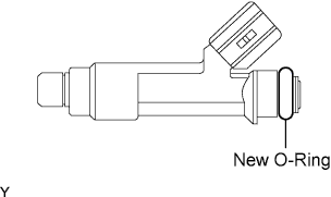
Apply a light coat of grease or gasoline to a new O-ring, and install it to the injector.
-
Apply a light coat of grease or gasoline to the place where the delivery pipe touches the O-ring.
-
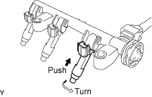
Push the fuel injector while twisting it back and forth to install it in the fuel delivery pipe.
Note
-
Be careful not to twist the O-ring.
-
After installing the fuel injector, check that it turns smoothly. If not, reinstall it with a new O-ring.
-
-
Position the injector connectors so that they face upward.
-
-
INSTALL FUEL DELIVERY PIPE
-
Install the 3 fuel injector vibration insulators to the cylinder head.
-
Place the fuel delivery pipe and the 3 fuel injectors together to the cylinder head.
Note
Be careful not to drop the fuel injectors when installing the fuel delivery pipe.
-
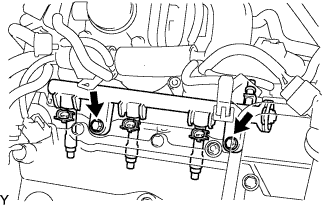
Temporarily install the 2 bolts which are used to hold the fuel delivery pipe to the cylinder head.
Note
After installing the fuel injector, check that it turns smoothly. If not, reinstall it with a new O-ring.
-
Tighten the 2 bolts which are used to hold the fuel delivery pipe to the cylinder head.
- Torque:
- 27 N*m { 275 kgf*cm, 20 ft.*lbf }
-
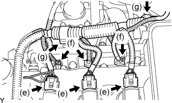
Connect the 3 ignition coil connectors.
-
Connect the 3 injector connectors and wire harness.
-
Connect the 2 clamps and wire harness.
-
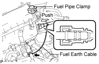
Push in the tube connector to the pipe until the tube connector makes a "click" sound.
Note
-
Check if there is any damage or foreign objects on the connected part of the fuel pipe.
-
After connecting, check that the fuel tube connector and the pipe are securely connected by pulling on them.
-
-
Install the fuel pipe clamp.
-
Connect the fuel earth cable to the heater hose pipe.
-
-
INSTALL THROTTLE BODY GASKET
-
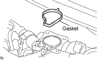
Install a new gasket on the intake manifold.
-
-
INSTALL THROTTLE BODY ASSEMBLY
-
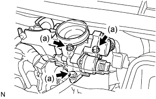
Install the throttle body with the 3 bolts.
- Torque:
- 10 N*m { 102 kgf*cm, 7 ft.*lbf }
-
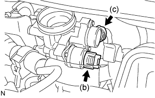
Connect the idle speed control valve connector.
-
Connect the throttle position sensor connector.
-
-
INSTALL ENGINE OIL LEVEL DIPSTICK GUIDE SUPPORT
-
Apply adhesive to the engine oil level dipstick guide support.
Adhesive Toyota Genuine Adhesive 1324, Three Bond 1324 or equivalent -
Install the engine oil level dipstick guide support.
-
-
INSTALL ENGINE OIL LEVEL DIPSTICK GUIDE
-
Install a new O-ring to the engine oil level dipstick guide.
-
Apply a light coat of engine oil to the O-ring.
-
Install the engine oil level dipstick guide with the bolt.
- Torque:
- 10 N*m { 102 kgf*cm, 7 ft.*lbf }
-
Connect the 2 clamps to the engine oil level dipstick guide.
-
-
INSTALL ENGINE OIL LEVEL DIPSTICK SUB-ASSEMBLY
-
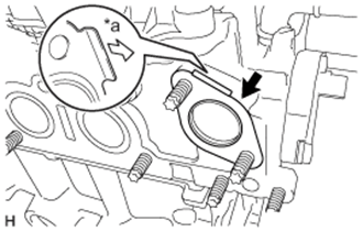
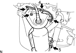
INSTALL NO. 1 WATER BY-PASS PIPE
-
Install a new water by-pass pipe gasket to the cylinder head as shown in the illustration.
Text in Illustration *a Water By-pass Pipe Side -
Connect the water by-pass hose with No. 1 water by-pass pipe to the timing chain cover with the hose clip.
-
Install the No. 1 water by-pass pipe with the bolt and 2 nuts.
- Torque:
- 24 N*m { 245 kgf*cm, 18 ft.*lbf }
-
-
INSTALL NO. 1 COMPRESSOR MOUNTING BRACKET (w/ Air Conditioning System)
-
Install the compressor mounting bracket with the 2 bolts.
- Torque:
- 25 N*m { 250 kgf*cm, 18 ft.*lbf }
-
-
INSTALL EXHAUST MANIFOLD
-
Install a new exhaust manifold gasket.
-
Install the exhaust manifold with the 3 bolts and 2 nuts in the order shown in the illustration.
- Torque:
- 24 N*m { 245 kgf*cm, 18 ft.*lbf }
-
-
INSTALL FAN BELT ADJUSTING BAR
-
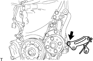
Instal the fan belt adjusting bar with the bolt.
- Torque:
- 34 N*m { 347 kgf*cm, 25 ft.*lbf }
-
-
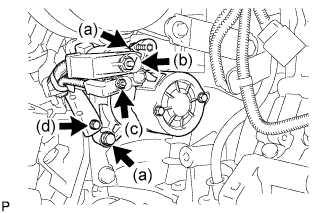
INSTALL GENERATOR ASSEMBLY
-
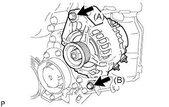
Install the generator with the 2 bolts.
- Torque:
- Bolt (A)
- 54 N*m { 551 kgf*cm, 40 ft.*lbf }
- Bolt (B)
- 34 N*m { 347 kgf*cm, 25 ft.*lbf }
-
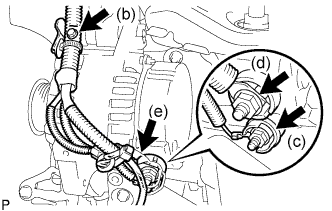
Install the wire harness clamp with the bolt.
- Torque:
- 8.4 N*m { 85 kgf*cm, 74 in.*lbf }
-
Install the generator wire with the nut to the terminal D.
- Torque:
- 4.5 N*m { 46 kgf*cm, 40 in.*lbf }
-
Install the generator wire with the nut to the terminal B.
- Torque:
- 9.0 N*m { 92 kgf*cm, 80 in.*lbf }
-
Install the terminal cap.
-
-
INSTALL SPARK PLUG
-
Install the 3 spark plugs.
- Torque:
- 25 N*m { 255 kgf*cm, 18 ft.*lbf }
Note
Do not use parts that have been dropped or received strong impact.
-
-
INSTALL NO. 1 IGNITION COIL
-
Install the 3 No. 1 ignition coils with the 3 bolts.
- Torque:
- 8.9 N*m { 91 kgf*cm, 79 in.*lbf }
-
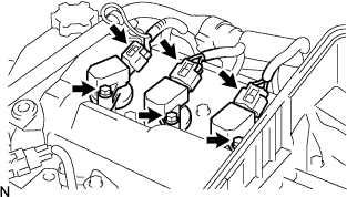
Connect the 3 connectors.
-
-
INSTALL FLYWHEEL SUB-ASSEMBLY
-
Clean the bolts and their holes.
-
Text in Illustration *1 Adhesive Apply adhesive to the 2 or 3 threads of the bolt end.
Adhesive Toyota Genuine Adhesive 1324, Three Bond 1324 or equivalent -
Using SST, hold the crankshaft.
- SST
- 09960-10010 ( 09962-01000, 09963-01000 )
-
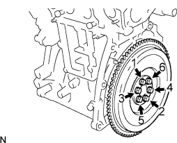
Install the flywheel sub-assembly with the 6 bolts in the order shown in the illustration.
- Torque:
- 78 N*m { 796 kgf*cm, 58 ft.*lbf }
-
-
INSTALL CLUTCH DISC ASSEMBLY
-
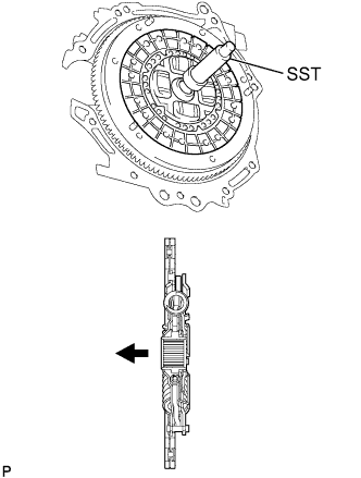
Insert SST into the clutch disc assembly, and then insert them into the flywheel sub-assembly.
Text in Illustration 
Flywheel Side - SST
- 09301-00131
Note
Do not insert the clutch disc assembly in the wrong direction.
-
-
INSTALL CLUTCH COVER ASSEMBLY
-
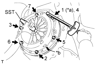
Text in Illustration *a Temporarily *b Matchmark Align the matchmark on the clutch cover assembly and the flywheel sub-assembly.
-
Tighten the 6 bolts uniformly in the order shown in the illustration, starting with the bolt located near the knock pin on the top.
- Torque:
- 19 N*m { 195 kgf*cm, 14 ft.*lbf }
Tech Tips
Move SST up and down, right and left gently after checking that the clutch disc assembly is in the center and tighten the bolts.
- SST
- 09301-00131
-
-
INSTALL MANUAL TRANSAXLE ASSEMBLY
-
Align the input shaft with the clutch disc assembly and install the manual transaxle assembly to the engine assembly.
-
Install the 5 bolts.
- Torque:
- 64 N*m { 653 kgf*cm, 47 ft.*lbf }
Note
-
Be careful not to pinch wire harnesses, etc.
-
Do not forcefully pry on the manual transaxle assembly.
-
To avoid damage to the input shaft, do not forcefully shake the manual transaxle assembly.
-
Insert knock pins into the knock pin holes securely so that the end face of the manual transaxle assembly fits close against the engine assembly before tightening the bolts.
-
-
INSTALL FLYWHEEL HOUSING UNDER COVER
-
Install the flywheel housing under cover to the manual transaxle assembly with the 3 bolts.
- Torque:
- 40 N*m { 408 kgf*cm, 30 ft.*lbf }
-
-
INSTALL FLYWHEEL HOUSING SIDE COVER
-
INSTALL STARTER ASSEMBLY
-
Install the starter with the 2 bolts.
- Torque:
- 37 N*m { 380 kgf*cm, 27 ft.*lbf }
-
Connect the wire harness to terminal 30 and install the nut.
- Torque:
- 9.5 N*m { 97 kgf*cm, 84 in.*lbf }
-
Connect the wire harness to terminal 50 and install the nut.
- Torque:
- 5.0 N*m { 51 kgf*cm, 44 in.*lbf }
-
Install the wire harness clamp with the bolt.
- Torque:
- 8.4 N*m { 85 kgf*cm, 74 in.*lbf }
-
-
INSTALL FRONT SUSPENSION CROSSMEMBER SUB-ASSEMBLY
-
Install the engine and transaxle assembly to the crossmember sub-assembly and the engine mounting member with the bolt.
- Torque:
- 120 N*m { 1224 kgf*cm, 89 ft.*lbf }
-
-
INSTALL ENGINE ASSEMBLY WITH TRANSAXLE
-
Set the engine lifter.
-
Remove the chain block from the engine assembly with transaxle.
-
Remove the 2 engine hangers and 2 bolts.
-
Operate the engine lifter and lift the engine assembly with transaxle and the front suspension crossmember to the position where the engine mounting insulators RH and LH can be installed.
-
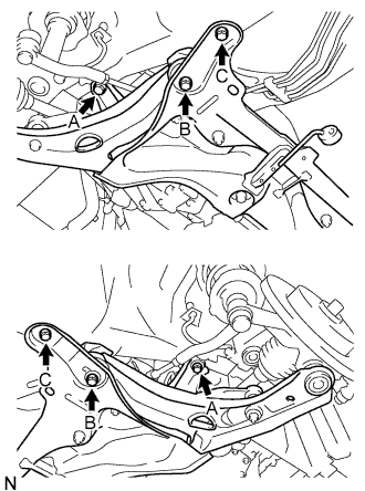
Install the front suspension crossmember with the 6 bolts.
- Torque:
- Bolt A
- 85 N*m { 867 kgf*cm, 63 ft.*lbf }
- Bolt B
- 128 N*m { 1306 kgf*cm, 95 ft.*lbf }
- Bolt C
- 48 N*m { 489 kgf*cm, 35 ft.*lbf }
-
Install the engine mounting insulator LH with the 7 bolts.
- Torque:
- 52 N*m { 530 kgf*cm, 38 ft.*lbf }
-
Install the engine mounting insulator RH with the 4 bolts and nut.
- Torque:
- 52 N*m { 530 kgf*cm, 38 ft.*lbf }
-
Remove the engine lifter.
-
-
INSTALL FRONT DRIVE SHAFT ASSEMBLY
-
INSTALL NO. 1 STEERING COLUMN HOLE COVER SUB-ASSEMBLY
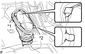
Text in Illustration *1 Clip A *2 Clip B
-
Install clip B onto the body and install the No. 1 steering column hole cover sub-assembly onto the body with clip A.
Note
Fit the lip of the No. 1 steering column hole cover sub-assembly correctly onto the dash panel.
-
-
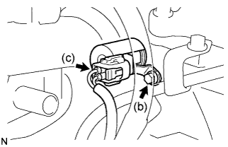
INSTALL NO. 2 STEERING INTERMEDIATE SHAFT ASSEMBLY
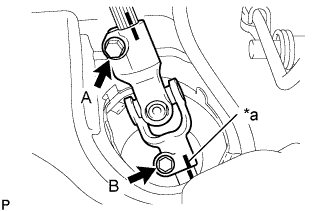
Text in Illustration *a Matchmark
-
Align the matchmarks and install the No. 2 steering intermediate shaft assembly to the steering gear assembly with bolt B.
- Torque:
- 35 N*m { 360 kgf*cm, 26 ft.*lbf }
-
Tighten bolt A.
- Torque:
- 35 N*m { 360 kgf*cm, 26 ft.*lbf }
-
Release the seat belt from the steering wheel assembly.
-
-
INSTALL STEERING COLUMN HOLE COVER PLATE
-
Engage the steering column hole cover plate.
-
-
CONNECT CLUTCH RELEASE CABLE ASSEMBLY
-
Install the clutch release cable assembly to the manual transaxle assembly.
-
-
INSTALL CLUTCH RELEASE FORK RETURN TENSION SPRING
-
Install the clutch release fork return tension spring to the release fork retracting spring hanger.
-
-
INSPECT AND ADJUST CLUTCH PEDAL SUB-ASSEMBLY
-
Turn up the floor carpet.
-
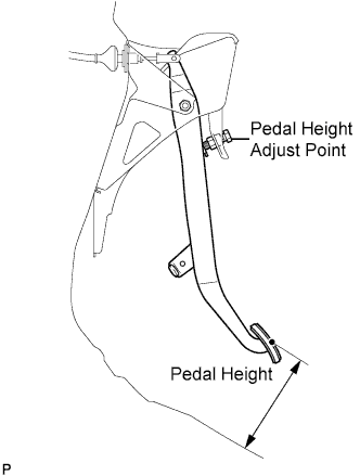
Check whether the pedal height is correct.
Pedal height from floor panel LHD 135 to 145 mm (5.31 to 5.71 in.) RHD 161 to 171 mm (6.34 to 6.74 in.) -
Adjust the pedal height.
-
Loosen the lock nut and turn the stopper bolt until the height is correct.
-
Tighten the lock nut.
- Torque:
- 25 N*m { 250 kgf*cm, 18 ft.*lbf }
-
-
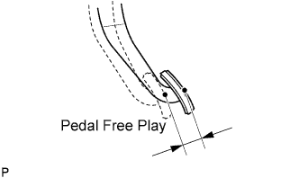
Check that the pedal free play is correct.
-
Depress the pedal until the resistance begins to be felt.
Pedal free play 13 to 23 mm (0.512 to 0.906 in.)
-
-
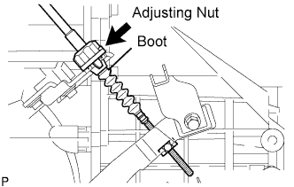
Adjust the pedal free play.
-
Turn the clutch release cable adjusting nut until the pedal free play is correct.
Note
Confirm that the clutch cable boot is installed.
-
After adjusting the pedal free play, check the pedal height.
-
-
Check the clutch release point.
-
Pull the parking brake lever and install the wheel stopper.
-
Start the engine and allow it to idle.
-
Without depressing the clutch pedal, slowly adjust the shift lever to the reverse position until the gears come into contact with the clutch pedal.
-
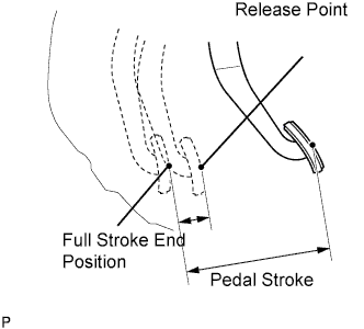
Gradually depress the clutch pedal and measure the stroke distance from the point that the gear noise stops (release point) up to the full stroke end position.
Standard distance 20 mm (0.787 in.) or more (from pedal stroke end position to release point) If the distance is not as specified, perform the following operations.
-
Check the pedal height.
-
Check the pedal free play.
-
Check the clutch cover and disc.
-
Check the pedal stroke.
Pedal stroke 148 mm (5.83 in.) -
-
-
-
INSTALL TRANSAXLE CONTROL CABLE ASSEMBLY
-
Connect the transmission control shift cable to the shift lever retainer.
-
Connect the transmission control shift cable to the floor shift shift lever.
-
Connect the transmission control select cable to the shift lever retainer.
-
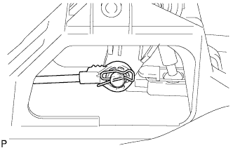
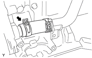
Connect the transmission control select cable to the floor shift shift lever.
Note
-
Connect the select cable point with the serrated part facing upwards.
-
Insert the clip in the orientation shown in the illustration.
-
-
-
CONNECT FUEL TUBE SUB-ASSEMBLY
-
Align the connector with the pipe, then push in the connector to the pipe until it makes a click sound to connect the fuel tube sub-assembly to the fuel delivery pipe.
Text in Illustration Push -
Install the fuel pipe clamp.
-
-
CONNECT HEATER WATER OUTLET HOSE A
-
Using pliers, grip the claws of the clip and slide the clip to connect the heater water outlet hose A.
-
-
CONNECT HEATER WATER HOSE INLET A
Tech Tips
Connection procedure for the heater water inlet hose A is the same as for the heater water outlet hose A.
-
CONNECT VACUUM HOSE ASSEMBLY
-
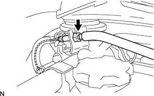
Align the connector with the pipe, then push in the connector to the pipe until it makes a click sound to connect the vacuum hose to the intake manifold.
Text in Illustration Push
-
-
INSTALL COMPRESSOR WITH PULLEY ASSEMBLY (w/ Air Conditioning System)
Text in Illustration *1 No. 1 Compressor Stay
-
Temporarily tighten the compressor with pulley assembly with the 3 bolts.
-
Temporarily tighten No. 1 compressor stay with the bolt and nut.
-
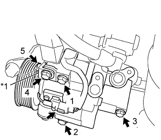
Fully tighten the 4 bolts and nut, in the order shown in the illustration.
- Torque:
- 25 N*m { 250 kgf*cm, 18 ft.*lbf }
-
Connect the connector.
-
-
INSTALL RADIATOR ASSEMBLY
-
INSTALL OUTLET RADIATOR HOSE
-
INSTALL INLET RADIATOR HOSE
-
INSTALL FRONT EXHAUST PIPE ASSEMBLY
-
INSTALL FAN AND GENERATOR V BELT
-

Text in Illustration *1 Generator Pulley *2 Idle Pulley *3 Compressor Pulley *4 Crankshaft Pulley *a No Measurable Clearance *b Specified Point *c w/ Air Conditioning System *d w/o Air Conditioning System Install the fan and generator V belt.
-
Loosely tighten the B bolt until there is no measurable clearance.
-
Turn the C bolt to adjust tension of the fan and generator V belt. Click here
-
Inspect the fan and generator V belt.
-
Tighten the B bolt.
- Torque:
- 34 N*m { 347 kgf*cm, 25 ft.*lbf }
-
Tighten the A bolt.
- Torque:
- 49 N*m { 500 kgf*cm, 36 ft.*lbf }
-
Visually check the generator wiring and listen for abnormal noise.
-
-
INSTALL FRONT BUMPER COVER
-
INSTALL NO. 2 FUEL VAPOR FEED HOSE
-
Connect the No. 2 fuel vapor feed hoses with the hose clip.
-
-
INSTALL NO. 1 FUEL VAPOR FEED HOSE
-
Connect the No. 1 fuel vapor feed hoses with the hose clip.
-
-
INSTALL ACCELERATOR CONTROL CABLE ASSEMBLY
-
Install the accelerator control cable assembly with the 2 nuts.
- Torque:
- 13 N*m { 133 kgf*cm, 10 ft.*lbf }
Tech Tips
Check that the throttle valve fully closes and opens with the control accelerator pedal.
-
-
INSTALL AIR CLEANER CAP SUB-ASSEMBLY
-
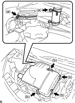
Install the air cleaner and air cleaner cap with the clamps.
-
Tighten the 4 clamps.
-
-
CONNECT ENGINE WIRE
-
Connect the battery terminal B with the nut.
- Torque:
- 14 N*m { 143 kgf*cm, 10 ft.*lbf }
-
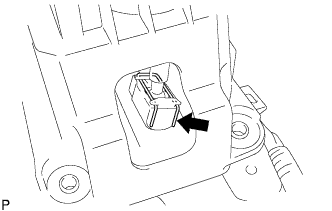
Connect the 2 connectors to the ECM, and slide the levers to engage the locks.
Note
Make sure that the levers are securely locked.
-
Engage the wire harness clamp.
-
Connect the 2 ground wires with the 2 bolts.
- Torque:
- 8.4 N*m { 86 kgf*cm, 74 in.*lbf }
-
Connect the ground wire to the transaxle with the bolt.
- Torque:
- 13 N*m { 130 kgf*cm, 9 ft.*lbf }
-
Engage the wire harness clamp.
-
-
INSTALL BATTERY CLAMP SUB-ASSEMBLY
-
Install the battery clamp sub-assembly with the 3 bolts.
- Torque:
- Bolt A
- 7.4 N*m { 75 kgf*cm, 65 in.*lbf }
- Bolt B
- 17 N*m { 175 kgf*cm, 13 ft.*lbf }
-
-
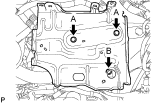
INSTALL ENGINE ROOM RELAY BLOCK
-
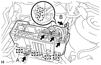
Engage the 4 wire harness clamps and install the engine room relay block.
-
Install the 2 bolts.
- Torque:
- Bolt A
- 5.4 N*m { 55 kgf*cm, 48 in.*lbf }
- Bolt B
- 8.4 N*m { 85 kgf*cm, 74 in.*lbf }
-
Engage the 2 claws and install the wire harness.
-
Connect the 3 connectors to the engine room relay block.
-
Install the engine room relay block cover.
-
-
INSTALL BATTERY
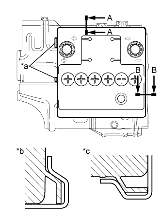
Text in Illustration *a Identification line *b A-A *c B-B
-
Install the battery onto the battery clamp sub-assembly, as shown in the illustration.
Note
-
The identification line should be seen after installing the battery.
-
The battery clamp should be in contact with the battery after the installation.
-
-
Install the battery clamp with the bolt.
- Torque:
- 15 N*m { 154 kgf*cm, 11 ft.*lbf }
-
Connect the battery positive (+) terminal with the nut.
- Torque:
- 5.4 N*m { 55 kgf*cm, 48 in.*lbf }
-
-
INSTALL COWL TOP PANEL OUTER
-
Install the cowl top panel outer with the 10 bolts.
- Torque:
- 9.2 N*m { 94 kgf*cm, 81 in.*lbf }
-
Engage the grommet and install the wire harness.
-
Engage the wire harness clamp.
-
-
INSTALL FRONT NO. 1 VENTILATOR SEAL
-
Install the No. 1 ventilator seal with the 2 clips.
-
-
INSTALL FRONT AIR SHUTTER SEAL RH
-
Install the front air shutter seal RH the 2 clips.
-
-
INSTALL FRONT WIPER MOTOR AND LINK ASSEMBLY
-
CONNECT CABLE FROM NEGATIVE BATTERY TERMINAL
- Torque:
- 5.4 N*m { 55 kgf*cm, 48 in.*lbf }
-
ADD MANUAL TRANSAXLE OIL
-
INSPECT MANUAL TRANSAXLE OIL
-
Stop the vehicle in a level place.
-
Remove the transmission filler plug and the gasket.
-
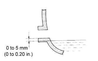
Check that the oil surface is within 5 mm (0.20 in.) of the bottom of the transmission filler plug opening.
Note
-
Excessively large or small amounts of oil may cause trouble.
-
After replacing the oil, drive the vehicle and check the oil level again.
-
-
Check for oil leakage if the oil level is low.
-
Install the transmission filler plug and a new gasket.
- Torque:
- 39 N*m { 400 kgf*cm, 29 ft.*lbf }
-
-
ADD ENGINE COOLANT
-
Connect the engine side radiator outlet hose .
-
Install the cylinder block drain cock plug.
- Torque:
- 20 N*m { 204 kgf*cm, 15 ft.*lbf }
-
Pour engine coolant into the radiator assembly until it is full.
Capacity Specification Capacity except Tropic Spec 4.0 liters (4.2 US qts, 3.5 Imp qts) for Tropic Spec 4.4 liters (4.6 US qts, 3.9 Imp qts) Note
Do not substitute water for engine coolant.
Tech Tips
-
Use of improper engine coolant may damage the engine cooling system.
-
Use only Toyota Super Long Life Coolant or similar high quality ethylene glycol based non-silicate, non-amine, non-nitrite, and non-borate engine coolant with long-life hybrid organic acid technology (coolant with long-life hybrid organic acid technology consists of a combination of low phosphates and organic acids).
-
-
Check the engine coolant level inside the radiator assembly by pressing the inlet and outlet radiator hoses several times by hand. If the engine coolant level goes down, add engine coolant.
-
Install the radiator cap sub-assembly securely.
-
Slowly pour engine coolant into the radiator reservoir until it reaches the FULL line.
-
Bleed air from the cooling system.
-
Warm up the engine until the thermostat opens.
While the thermostat is open, circulate the coolant for several minutes.
-
The thermostat open timing can be confirmed by pressing the outlet radiator hose by hand, and checking when the coolant starts to flow inside the hose.
-
Maintain the engine speed at 2500 to 3000 rpm and warm up the engine until the cooling fan operates.
-
Press the outlet radiator hose and inlet radiator hose several times by hand to bleed air.
CAUTION:
When pressing the radiator hoses:
-
Wear protective gloves.
-
Be careful as the radiator hoses are hot.
-
Keep your hands away from the radiator fan.
-
-
-
Stop the engine and wait until the coolant cools down.
-
If the engine coolant level is below the full level, perform steps (c) through (h) and repeat the operation until the engine coolant level stays the full level.
-
Recheck the engine coolant level inside the radiator reservoir tank assembly. If it is below the full level, add engine coolant.
-
-
INSPECT FOR ENGINE COOLANT LEAK
CAUTION:
To avoid the danger of being burned, do not remove the radiator cap sub-assembly while the engine and radiator assembly are still hot. Thermal expansion will cause hot engine coolant and steam to blow out from the radiator assembly.
-
Fill the radiator assembly with engine coolant and attach a radiator cap tester.
-
Pump the tester to 137 kPa (1.4 kgf*cm2 , 19.9 psi), then check that the pressure does not drop. If the pressure drops, check the hoses, radiator assembly and water pump assembly for leakage. If there are no signs or traces of external engine coolant leakage, check the heater core, cylinder block and head.
-
-
INSPECT FOR ENGINE OIL LEAK
-
INSPECT FOR EXHAUST GAS LEAK
-
INSPECT FOR FUEL LEAK
-
INSPECT IGNITION TIMING
Note
-
Turn all the electrical system and the A/C off.
-
Inspect the ignition timing with the cooling fan off.
-
When checking the ignition timing, shift the transmission to the neutral position.
-
Warm up and stop the engine.
-
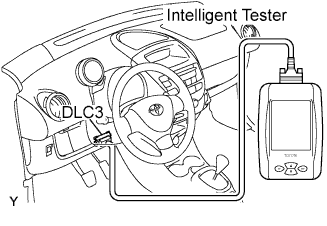
When using the intelligent tester:
-
Connect the intelligent tester to the DLC3.
-
Turn the ignition switch on.
-
Select the item:
Powertrain / Engine and ETC / Active Test / TE1 (TC) / ON.
Tech Tips
Refer to the intelligent tester operator's manual if you need help to select Active Test.
-
Inspect the ignition timing at idle.
Ignition timing 8 to 12 degrees BTDC -
Select the item:
TE1 (TC) / OFF
-
Turn the ignition switch off.
-
Disconnect the intelligent tester from the DLC3.
-
-
When not using the intelligent tester:
-
Remove the air cleaner cap sub-assembly Click here.
-
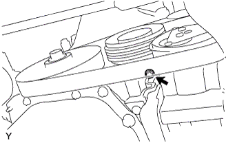
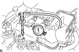
Install the tester terminal of a timing light to the position shown in the illustration.
Note
-
Use a timing light that detects the first signal.
-
After checking, be sure to wrap the wire harness with tape.
-
-
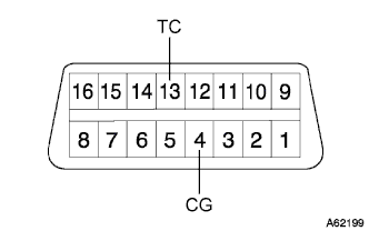
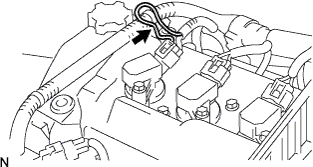
Using SST, connect terminals 13 (TC) and 4 (CG) of the DLC3.
- SST
- 09843-18040
Note
Make sure of the terminal numbers before connecting them. Connecting the wrong terminals can damage the engine.
-
Turn the ignition switch on.
-
Inspect the ignition timing at idle.
Ignition timing 8 to 12 degrees BTDC Tech Tips
Run the engine speed at 1,000 to 1,300 rpm for 5 seconds, then check that the engine speed returns to the idle speed.
-
Disconnect terminals 13 (TC) and 4 (CG) of the DLC3.
-
Turn the ignition switch off.
-
Remove the timing light.
-
Install the air cleaner cap sub-assembly Click here.
-
-
-
INSPECT ENGINE IDLE SPEED
Note
-
Turn all the electrical system and the A/C OFF.
-
Inspect the engine idle speed with the cooling fan OFF.
-
When checking the idle speed, shift the transmission to the neutral position.
-
Warm up and stop the engine.
-

When using the intelligent tester:
-
Connect the intelligent tester to the DLC3.
-
Turn the ignition switch on.
-
Select the item:
Powertrain / Engine and ECT / Data List / Engine SPD.
Tech Tips
Refer to the intelligent tester operator's manual if you need help to select Data List.
-
Inspect the engine idle speed.
Idle speed 790 to 890 rpm -
Turn the ignition switch off.
-
Disconnect the intelligent tester from the DLC3.
-
-
When not using the intelligent tester:
-
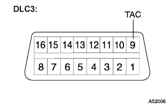
Install SST to terminal 9 (TAC) of the DLC3, then connect a tachometer.
- SST
- 09843-18040
Note
Make sure of the terminal numbers before connecting them. Connecting the wrong terminals can damage the engine.
-
Turn the ignition switch on.
-
Inspect the engine idling speed.
Idle speed 790 to 890 rpm -
Turn the ignition switch off.
-
Disconnect a tachometer.
-
Remove SST from terminal 9 (TAC).
-
-
-
INSPECT COMPRESSION
-
Warm up and stop the engine.
-
Remove the air cleaner cap sub-assembly Click here.
-
Remove the 3 ignition coils Click here.
-
Remove the 3 spark plugs.
-
Disconnect the 3 fuel injector connectors.
-
Inspect cylinder compression pressure.
-
Insert a compression gauge into the spark plug hole.
-
Fully open the throttle.
-
While cranking the engine, measure the compression pressure.
Compression pressure (Normal condition) 1,422 kPa (14.5 kgf/cm2, 206 psi) Minimum pressure 1,079 kPa (11.0 kgf/cm2, 156 psi) Difference between each cylinder 147 kPa (1.5 kgf/cm2, 21 psi) or less Note
-
Use a fully-charged battery so the engine speed can be increased to 400 rpm or more.
-
Inspect the other cylinders in the same way.
-
Measure the compression as quickly as possible.
-
-
If the cylinder compression is low, pour a light coat of engine oil into the cylinder through the spark plug hole, then inspect it again.
Tech Tips
-
If adding oil increases the compression, the piston rings and/or cylinder bore may be worn or damaged.
-
If pressure stays low, the valve may be stuck or seated improperly, or there may be leakage from the gasket.
-
-
-
Connect the 3 fuel injector connectors.
-
Install the 3 spark plugs.
- Torque:
- 25 N*m { 255 kgf*cm, 18 ft.*lbf }
-
Install the 3 ignition coils Click here.
-
Install the air cleaner cap sub-assembly Click here.
-
-
INSPECT CO/HC
Tech Tips
The ECM properly controls the CO/HC concentration in the emission gas.
-
Start the engine.
-
Run the engine at 2,500 rpm for approximately 180 seconds.
-
Insert the CO/HC meter testing probe at least 40 cm (1.3 ft) into the tailpipe while idling.
-
Check the CO/HC concentration at idle.
Standard CO concentration 0.2% or less HC concentration 70 ppm or less If the CO/HC concentration does not comply with the regulations, troubleshoot in the order given below.
-
Check the heated oxygen sensor operation Click here.
-
See the table below for possible causes, then inspect the applicable causes and repair them if necessary.
CO HC Problems Causes Normal High Rough idle
-
Faulty ignitions:
-Fouled, shorted or improperly gapped plugs
-
Incorrect valve clearance
-
Leaks in intake and exhaust valves
-
Leaks in cylinders
Low High Rough Idle
(Fluctuating HC reading)
-
Lean mixture causing misfire
-
Faulty SFI systems:
-Faulty pressure regulator
-Defective engine coolant temperature sensor
-Detective mass air flow meter
-Faulty ECM
-Faulty injectors
-Faulty throttle body
High High Rough idle
(Black smoke from exhaust)
-
Faulty SFI systems:
-Faulty pressure regulator
-Defective engine coolant temperature sensor
-Detective mass air flow meter
-Faulty ECM
-Faulty injectors
-Faulty throttle body
-
-
-
INSPECT AND ADJUST FRONT WHEEL ALIGNMENT