COMMON RAIL INSTALLATION

-
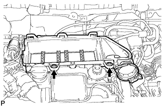
INSTALL COMMON RAIL ASSEMBLY
-
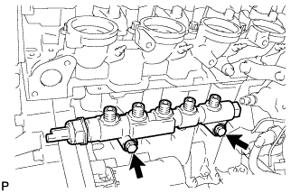
Install the common rail assembly with the 2 bolts.
- Torque:
- 23 N*m { 235 kgf*cm, 17 ft.*lbf }
-
Temporarily install 5 new injection pipes with the union nuts.
Note
-
Keep the joints of the injection pipes clean.
-
Screw on by hand, to the end of the thread, the unions of the injection pipes on the injectors side and on the common rail side.
Note
Keep the joints of the injection pipes clean.
-
-
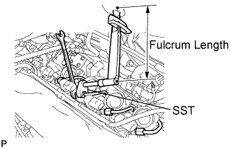
Using SST, tighten the 4 union nuts at the injector end of the injection pipes.
- SST
- 09023-38401
- Torque:
- When using SST
- 17 N*m { 173 kgf*cm, 13 ft.*lbf }
- When not using SST
- 19 N*m { 194 kgf*cm, 14 ft.*lbf }
Tech Tips
Use a torque wrench with a fulcrum length of 300 mm (11.81 in.).
-
Using SST, retighten the 4 union nuts at the injector end of the injection pipes.
- SST
- 09023-38401
- Torque:
- When using SST
- 23 N*m { 232 kgf*cm, 17 ft.*lbf }
- When not using SST
- 25 N*m { 255 kgf*cm, 18 ft.*lbf }
Tech Tips
Use a torque wrench with a fulcrum length of 300 mm (11.81 in.).
-
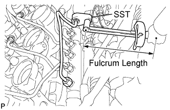
Using SST, tighten the union nut at the supply pump end of the injection pipe.
- SST
- 09023-38401
- Torque:
- When using SST
- 17 N*m { 173 kgf*cm, 13 ft.*lbf }
- When not using SST
- 19 N*m { 194 kgf*cm, 18 ft.*lbf }
Tech Tips
Use a torque wrench with a fulcrum length of 300 mm (11.81 in.).
-
Using SST, retighten the union nut at the supply pump end of the injection pipe.
- SST
- 09023-38401
- Torque:
- When using SST
- 23 N*m { 235 kgf*cm, 17 ft.*lbf }
- When not using SST
- 25 N*m { 255 kgf*cm, 18 ft.*lbf }
Tech Tips
Use a torque wrench with a fulcrum length of 300 mm (11.81 in.).
-
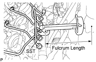
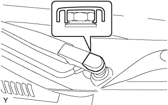
Using SST, tighten the 5 union nuts at the common rail end of the injection pipes.
- SST
- 09023-12701
- Torque:
- When using SST
- 17 N*m { 173 kgf*cm, 13 ft.*lbf }
- When not using SST
- 19 N*m { 194 kgf*cm, 14 ft.*lbf }
Tech Tips
Use a torque wrench with a fulcrum length of 345 mm (13.58 in.).
-
Using SST, retighten the 5 union nuts at the common rail end of the injection pipes.
- SST
- 09023-12701
- Torque:
- When using SST
- 23 N*m { 235 kgf*cm, 17 ft.*lbf }
- When not using SST
- 25 N*m { 255 kgf*cm, 18 ft.*lbf }
Tech Tips
Use a torque wrench with a fulcrum length of 345 mm (13.58 in.).
-
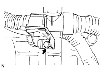
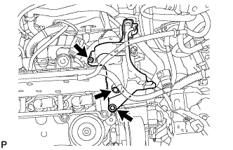
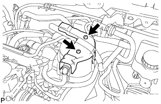
Install the water outlet box support with the bolt.
- Torque:
- 18 N*m { 184 kgf*cm, 13 ft.*lbf }
-
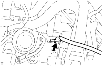
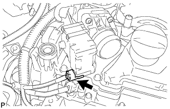
Connect the fuel pressure sensor connector.
-
-
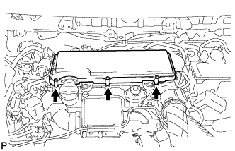
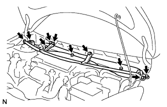
INSTALL CYLINDER HEAD COVER SUB-ASSEMBLY
-
Apply a light coat of engine oil to a new gasket and 4 new O-rings, and install them to the cylinder head cover sub-assembly.
-
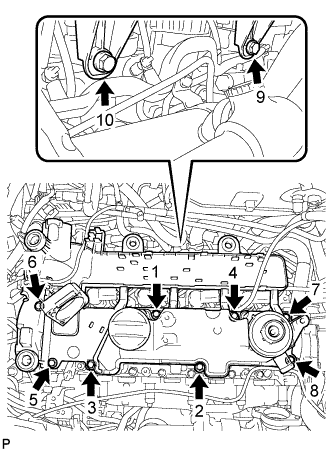
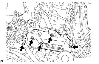
Temporarily install the cylinder head cover sub-assembly with the 10 bolts.
-
Tighten the 10 bolts in the order shown in the illustration.
- Torque:
- 10 N*m { 102 kgf*cm, 7 ft.*lbf }
-
-
INSTALL FUEL TEMPERATURE SENSOR
-
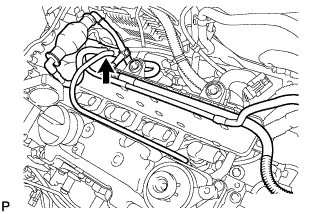
Install the fuel temperature sensor to the cylinder head cover sub-assembly.
-
Connect the fuel return tube to the fuel temperature sensor.
-
-
INSTALL TIMING BELT UPPER COVER
-
Install the timing belt cover sub-assembly with the 5 bolts.
- Torque:
- 5.0 N*m { 51 kgf*cm, 44 in.*lbf }
-
-
INSTALL WIRE HARNESS AND CONNECTOR
-
Install the wire harness clamp.
-
Connect the wire harness clamp.
-
Connect the 4 wire harness clamps.
-
Connect the camshaft position sensor connector.
-
-
INSTALL RADIATOR RESERVOIR TANK ASSEMBLY
-
Install the radiator reserve tank with the bolt.
- Torque:
- 7.5 N*m { 77 kgf*cm, 66 in.*lbf }
-
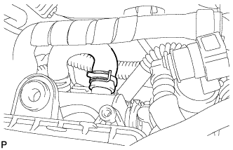
Insert the 2 water by-pass hoses.
-
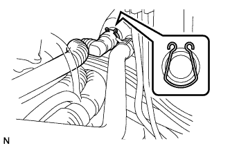
Install the 2 clips.
-
Insert the fuel by-pass hose No.5.
-
Install the clip.
-
-
INSTALL EGR VALVE ASSEMBLY W/ EGR COOLER
-
Apply a light coat of engine oil to a new O-ring.
-
Install the O-ring to the EGR cooler pipe.
-
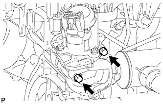
Temporarily install the EGR valve assembly w/ EGR cooler and a new gasket with the 2 bolts.
-
Temporarily install the wire harness bracket with the bolt.
-
Tighten the EGR valve assembly w/ EGR cooler with the 2 bolts.
- Torque:
- 6.0 N*m { 61 kgf*cm, 53 in.*lbf }
-
Using a "torx" socket wrench, install the 2 screws.
- Torque:
- 5.0 N*m { 51 kgf*cm, 44 in.*lbf }
-
Connect the EGR valve connector.
-
-
CONNECT ECM CONNECTOR
-
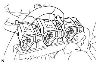
Connect the 3 ECM connectors.
Note
-
Check the ECM and the area around the ECM for water or dirt. Clean them as necessary.
-
Check the connection of the removed ECM connector for water or dirt. Clean it as necessary.
-
-
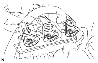
Turn the retainers and securely lock the connectors.
-
-
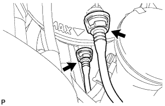
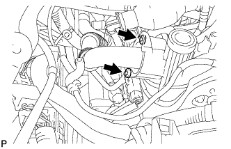
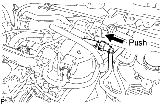
CONNECT WATER HOSE
-
Match the axis of the connector with the axis of the pipe, and push into the connector until the connector makes a "click" sound. If the connection is excessively tight, apply a small amount of engine coolant to the tip of the pipe.
-
After finishing the connection, check that the pipe and the connector are securely connected by pulling on them.
-
-
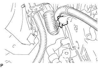
CONNECT WATER BY-PASS HOSE
-
Connect the EGR cooler water by-pass hose with the clip.
-
-
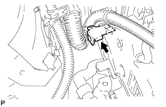
CONNECT HEATER HOSE
-
Connect the heater hose with the clip.
-
-
INSTALL WIRE HARNESS CLAMP BRACKET
-
Tighten the wire harness clamp bracket with the bolt.
- Torque:
- 6.0 N*m { 61 kgf*cm, 53 in.*lbf }
-
Connect the wire harness clamp.
-
-
INSTALL THROTTLE VALVE (FOR EGR)
-
Apply a light coat of engine oil to a new O-ring.
-
Install the O-ring to the throttle valve.
-
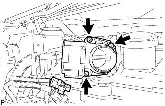
Using a "torx" socket wrench, install the throttle valve with the 3 screws.
-
Connect the throttle valve connector.
-
-
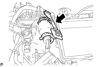
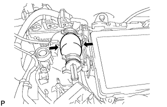
INSTALL INTAKE AIR RESONATOR
-
Apply a light coat of engine oil to a new O-ring.
-
Install the O-ring to the intake air resonator.
-
Install the intake air resonator to the turbocharger as shown in the illustration.
-
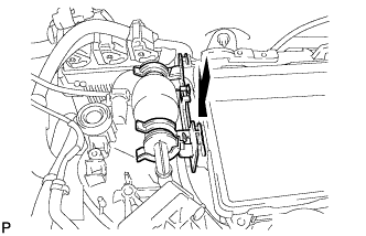
Temporarily install the intake air resonator.
-
Tighten the clamp.
- Torque:
- 3.5 N*m { 36 kgf*cm, 31 in.*lbf }
-
Tighten the bolt.
- Torque:
- 7.5 N*m { 76 kgf*cm, 66 in.*lbf }
-
Using a "torx" socket wrench, tighten the screw.
- Torque:
- 7.5 N*m { 76 kgf*cm, 66 in.*lbf }
-
Connect the turbocharger air temperature sensor connector.
-
Connect the water reservoir tube to the intake air resonator.
-
-
INSTALL FUEL FILTER BRACKET
-
Install the fuel filter bracket with the 2 bolts.
- Torque:
- 10 N*m { 102 kgf*cm, 7 ft.*lbf }
-
Using a "torx" socket wrench, install the screw.
- Torque:
- 5.0 N*m { 51 kgf*cm, 44 in.*lbf }
-
-
CONNECT WIRE HARNESS
-
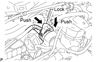
Connect the connector and push down the lock.
-
-
INSTALL FUEL FILTER
-
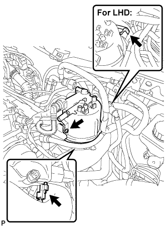
Connect the fuel heater connector.
-
For LHD:
-
Connect the fuel filter warning switch connector.
-
-
Using a "torx" socket wrench, install the fuel filter with the screw.
- Torque:
- 5.0 N*m { 51 kgf*cm, 44 in.*lbf }
-
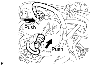
Push the 2 tube connectors into the 2 pipes until the tube connectors make a "click" sound.
Note
-
Before installing the pipe, make sure that it is not damaged. Make sure that there is no dirt present on the connecting surfaces.
-
After connecting, check that the fuel tube connector and the pipe are securely connected by pulling on them.
-
-
-
INSTALL FUEL FILTER PROTECTOR
-
Using a "torx" socket wrench, install the fuel tank protector with the 2 screws.
- Torque:
- 2.0 N*m { 20 kgf*cm, 18 in.*lbf }
-
-
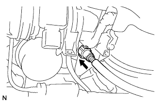
CONNECT FUEL HOSE
-
Push the tube connector into the pipe until the tube connector makes a "click" sound.
Note
-
Before installing the pipe, make sure that it is not damaged. Make sure that there is no dirt present on the connecting surfaces.
-
After connecting, check that the fuel tube connector and the pipe are securely connected by pulling on them.
-
-
-
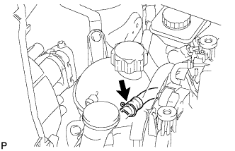
CONNECT VACUUM HOSE ASSEMBLY
-
Align the connector with the pipe, then push in the connector to the pipe until it makes a "click" sound to connect the vacuum hose assembly to the vacuum pump.
-
-
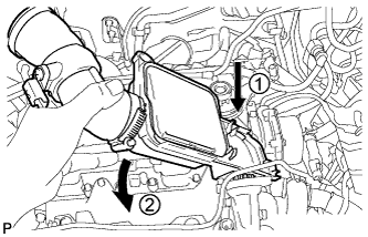
INSTALL AIR CLEANER CASE
-
Install the air cleaner case, and connect the 2 wire harness clamps.
-
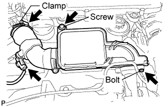
Using a "torx" socket wrench, install the air cleaner case with the 2 screws.
- Torque:
- 5.0 N*m { 51 kgf*cm, 44 in.*lbf }
-
-
INSTALL PRIMING PUMP BRACKET
-
Install the priming pump bracket.
-
Install the priming pump bracket to the air cleaner case.
-
-
INSTALL TURBO PRESSURE SENSOR
-
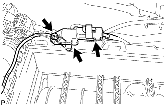
Install the turbo pressure sensor with the screw.
- Torque:
- 4.0 N*m { 41 kgf*cm, 35 in.*lbf }
-
Connect the turbo pressure sensor connector and hose.
-
-
INSTALL INLET AIR CLEANER NO.2
-
Install the inlet air cleaner No.2.
-
Using a "torx" socket wrench, install the inlet air cleaner No.2 with the screw.
- Torque:
- 5.0 N*m { 51 kgf*cm, 44 in.*lbf }
-
-
INSTALL INLET AIR CLEANER
-
Install inlet air cleaner.
-
-
INSTALL ENGINE ROOM RELAY BLOCK
-
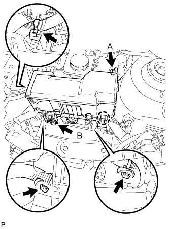
Connect the 3 wire harness clamps.
-
Engage the claw and install the engine room relay block with the 2 bolts.
- Torque:
- Bolt A
- 8.4 N*m { 86 kgf*cm, 74 in.*lbf }
- Bolt B
- 5.4 N*m { 55 kgf*cm, 48 in.*lbf }
-
-
INSTALL MASS AIR FLOW METER
-
Apply a light coat of engine oil to a new O-ring.
-
Install the O-ring to the mass air flow meter.
-
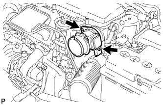
Using a "torx" socket wrench, install the mass air flow meter with the 2 screws.
- Torque:
- 3.5 N*m { 36 kgf*cm, 31 in.*lbf }
-
Connect the mass air flow meter connector.
-
-
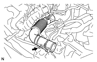
INSTALL AIR HOSE
-
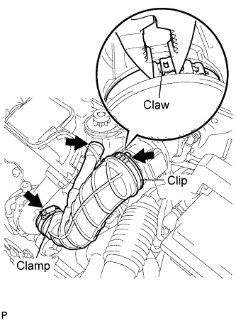
Install the air hose with the clamp and a new clip.
- Torque:
- Clamp
- 5.0 N*m { 51 kgf*cm, 44 in.*lbf }
-
-
INSTALL AIR CLEANER CAP
-
Using a "torx" socket wrench, install the air cleaner cap with the 3 screws.
- Torque:
- 5.0 N*m { 51 kgf*cm, 44 in.*lbf }
-
-
INSTALL BATTERY
-
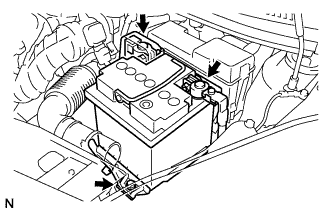
Install the battery and clamp with the bolt.
- Torque:
- 15 N*m { 154 kgf*cm, 11 ft.*lbf }
-
Connect the positive battery cable.
- Torque:
- 5.4 N*m { 55 kgf*cm, 48 in.*lbf }
-
-
ADD ENGINE COOLANT
-
Install the drain plug with an O-ring and a new clip.
-
Connect the radiator hose No.2.
-
Pour engine coolant into the reserve tank assembly.
Capacity 4.0 to 4.4 L Note
Do not substitute water for engine coolant.
Tech Tips
-
Use of improper engine coolant may damage the engine coolant system.
-
Use only Premium Long Life Coolant for 1WZ and 2WZ-TV. Pre-mixed. Green. or similar high quality ethylene glycol based non-silicate, non-amine, non-nitrite, and non-borate engine coolant with long-life hybrid organic acid technology (coolant with long-life hybrid organic acid technology consists of a combination of low phosphates and organic acids).
-
-
Check the engine coolant level inside the radiator assembly by pressing the inlet and outlet radiator hoses several times by hand. If the engine coolant level goes down, add engine coolant.
-
Connect the water by-pass hose with the hose clamp.
Tech Tips
Connect the water by-pass hose, when the fluid flows clean and without air bubbles.
-
Slowly pour engine coolant into the radiator reservoir until it reaches the FULL line.
-
Install the reservoir tank cap sub-assembly securely.
-
-
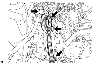
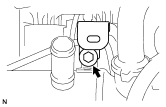
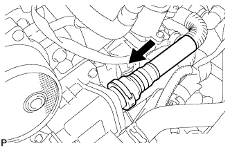
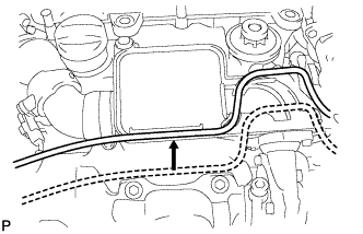
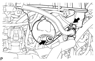
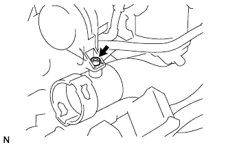
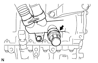
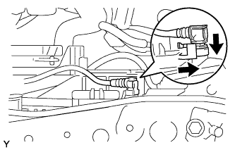
BLEED FUEL SYSTEM
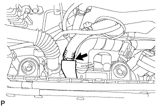
-
Using the hand pump indicated by the arrows in the illustration, bleed the fuel system. Continue pumping until pumping becomes difficult.
-
-
CHECK FOR FUEL LEAKS
-
Check that there are no leaks from any part of the fuel system when the engine is stopped.
If there is fuel leakage, repair or replace parts as necessary.
-
Start the engine and check that there are no leaks from any part of the fuel system.
If there is fuel leakage, repair or replace parts as necessary.
-
Depress the accelerator pedal and rev up the 4000 rpm. After driving the vehicle, check for fuel leakage.
If there is excessive fuel leakage, repair or replace parts as necessary.
-
-
CHECK FOR OIL LEAKS
-
CHECK FOR ENGINE COOLANT LEAKS
-
Start the engine.
-
Maintain the engine speed at 1,500 rpm until the first cooling cycle (cooling fan on).
-
Stop the engine and wait for cool down.
-
If necessary top up the level to the maximum mark.
-
-
INSTALL ENGINE COVER
-
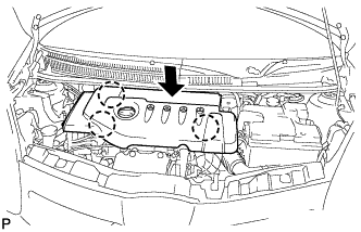
Align the 3 claws to install the engine cover.
-
-
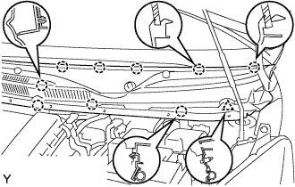
INSTALL COWL TOP PANEL OUTER
-
Install the cowl top panel outer with the 10 bolts.
- Torque:
- 9.2 N*m { 94 kgf*cm, 81 in.*lbf }
-
-
INSTALL FRONT WIPER MOTOR AND LINK ASSEMBLY
-
Connect the connector.
-
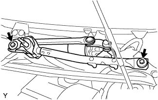
Install the front wiper motor and link assembly with the 2 bolts.
- Torque:
- 13 N*m { 127 kgf*cm, 9 ft.*lbf }
-
-
INSTALL COWL TOP VENTILATOR LOUVER RH
-
Connect the washer hose.
-

Engage the 8 claws and install the cowl top ventilator louver RH.
-
Install the clip.
-
-
INSTALL COWL TOP VENTILATOR LOUVER LH
-
Connect the washer hose.
-
Engage the 9 claws and install the cowl top ventilator louver LH.
-
Install the clip.
-
-
INSTALL HOOD TO COWL TOP SEAL

-
Engage the 8 clips and install the hood to cowl top seal.
-
-
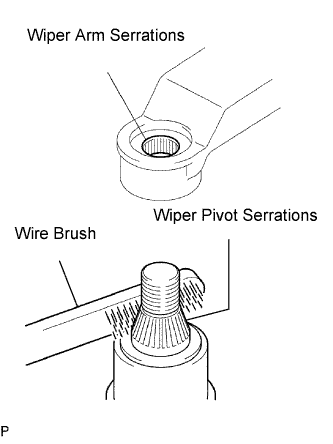
INSTALL FR WIPER ARM LH
-
Scrape any metal powder off the serrated part of the wiper arm with a round file or equivalent (when reinstalling).
-
Clean the wiper pivot serrations with a wire brush.
-
Operate the wiper, then stop the windshield wiper motor assembly in the automatic stop position.
-
Provisionally install the front wiper main arm with the nut.
-
Install the front wiper secondary arm onto the front wiper motor and link assembly.
-
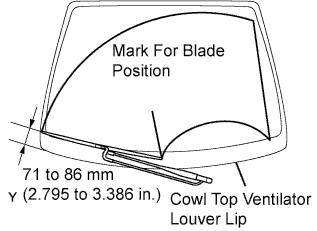
Align the blade tip with the mark on the windshield glass, as shown in the illustration.
-
Tighten the nut of the front wiper main arm.
- Torque:
- 21 N*m { 209 kgf*cm, 15 ft.*lbf }
-
-
INSTALL FRONT WIPER HEAD CAP
-
Engage the claw and install the front wiper arm head cap.
-