COMMON RAIL REMOVAL

Note
-
Do not use an ohmmeter to check the sensor.
-
Checking the sensor with an ohmmeter could damage the sensor.
-
REMOVE BATTERY
-
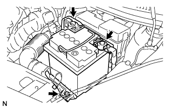
Disconnect the negative battery cable.
-
Disconnect the positive battery cable.
-
Remove the bolt, clamp and battery.
-
-
DRAIN ENGINE COOLANT
Note
To avoid the danger of being burned, do not remove the reservoir tank cap sub-assembly while the engine and radiator assembly are still hot. Thermal expansion will cause hot engine coolant and steam to blow out from the radiator assembly.
-
Remove the drain plug and clip, then drain the engine coolant.
-
Disconnect the radiator by uncoupling the radiator hose No.2.
-
Remove the hose clamp, disconnect the water by-pass hose.
-
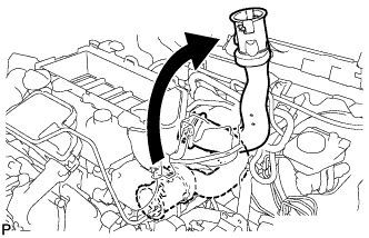
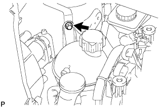
Remove the reservoir tank cap sub-assembly.
-
-
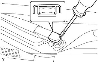
REMOVE FRONT WIPER HEAD CAP
-
Using a screwdriver with its tip wrapped in protective tape, remove the front wiper arm head cap.
-
-
REMOVE FRONT WIPER ARM LH
-
Operate the wiper, then stop the windshield wiper motor assembly in the automatic stop position.
-
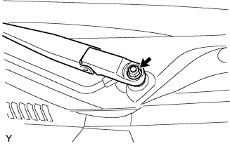
Remove the nut and front wiper main arm.
-
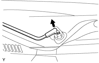
Disengage the meshing of the secondary arm from the front wiper motor and link assembly.
Note
Do not bend the secondary arm when removing it.
-
-
REMOVE HOOD TO COWL TOP SEAL

-
Disengage the 8 clips and remove the hood to cowl top seal.
-
-
REMOVE COWL TOP VENTILATOR LOUVER LH

-
Remove the clip.
-
Disengage the 8 claws and remove the cowl top ventilator louver RH.
-
Disconnect the washer hose.
-
-
REMOVE COWL TOP VENTILATOR LOUVER RH
-
Remove the clip.
-
Disengage the 8 claws and remove the cowl top ventilator louver RH.
-
Disconnect the washer hose.
-
-
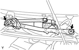
REMOVE FRONT WIPER MOTOR AND LINK ASSEMBLY
-
Remove the 2 bolts.
-
Disconnect the connector and remove the front wiper motor and link assembly.
-
-
REMOVE COWL TOP PANEL OUTER
-
Remove the 10 bolts and cowl top panel outer.
-
-
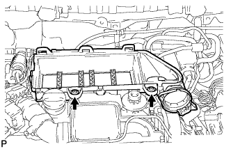
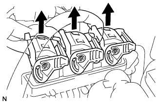
REMOVE ENGINE COVER
-
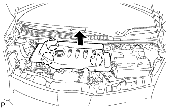
Disengage the 3 claws and remove the engine cover.
-
-
REMOVE AIR CLEANER CAP
-
Using a "torx" socket wrench, loosen the 3 screws, and remove the air cleaner cap.
-
-
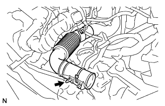
REMOVE AIR HOSE
-
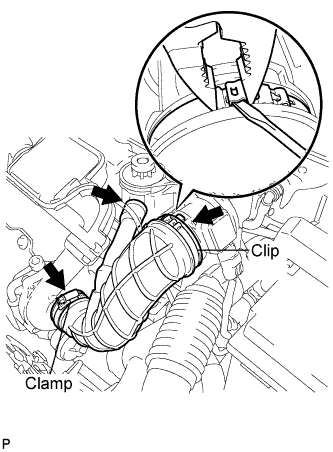
Loosen the clamp bolt.
-
Using a screwdriver and pliers, remove the clip.
-
Remove the air hose.
-
-
REMOVE MASS AIR FLOW METER
-
Disconnect the mass air flow meter connector.
-
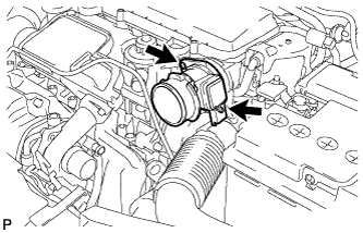
Using a "torx" socket wrench, remove the 2 screws and the mass air flow meter.
-
Remove the O-ring from the mass air flow meter.
-
-
SEPARATE ENGINE ROOM RELAY BLOCK
-
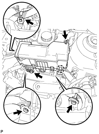
Remove the 2 bolts and disengage the claw.
-
Separate the 3 wire harness clamps and the engine room relay block.
-
-
REMOVE INLET AIR CLEANER
-
Remove the inlet air cleaner.
-
-
REMOVE INLET AIR CLEANER NO.2
-
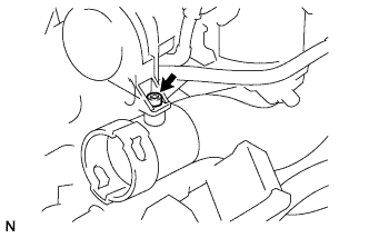
Using a "torx" socket wrench, remove the screw.
-
Turn the inlet air cleaner No.2.
-
Remove the inlet air cleaner No.2.
-
-
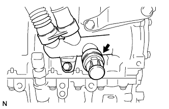
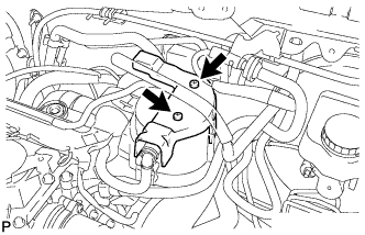
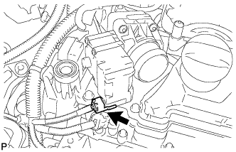
REMOVE TURBO PRESSURE SENSOR
-
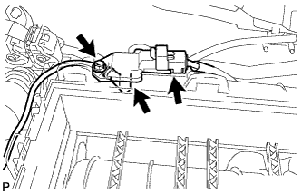
Disconnect the turbo pressure sensor connector.
-
Remove the screw and disconnect the hose to remove the turbo pressure sensor.
-
-
REMOVE PRIMING PUMP BRACKET
-
Separate the priming pump bracket from the air cleaner case.
-
Remove the priming pump bracket.
-
-
REMOVE AIR CLEANER CASE
-
Using a "torx" socket wrench, loosen the 2 screws.
-
Remove the 2 wire harness clamps and the air cleaner case.
-
-
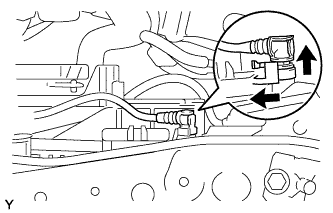
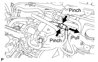
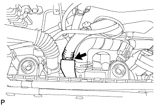
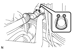
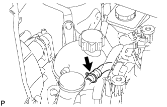
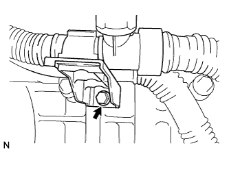
DISCONNECT VACUUM HOSE ASSEMBLY
-
Pinch the retainer as illustrated, then pull out the vacuum hose connector from the pipe.
-
-
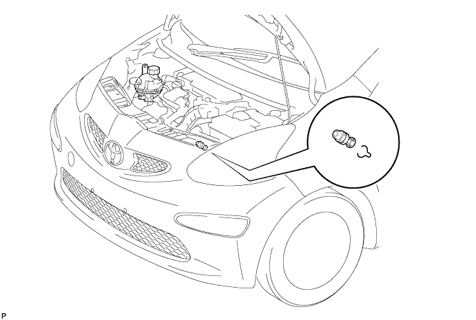
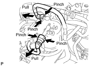
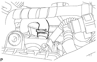
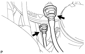
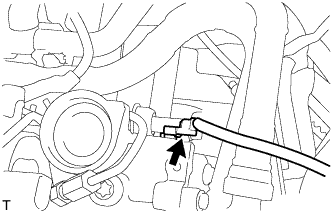
DISCONNECT FUEL HOSE
-
Pinch the tube connector and then pull out the fuel hose.
Note
-
Check if there is any dirt or other foreign objects around the connector before this operation and clean the connector as necessary.
-
Remove the quick connector by hand.
-
Do not bend or twist the nylon tube. Protect the connector by covering it with a plastic bag.
-
If the pipe and the connector are stuck, try wiggling or pushing and pulling the connector to release it and pull the connector off of the pipe carefully.
-
-
-
REMOVE FUEL FILTER PROTECTOR
-
Using a "torx" socket wrench, remove the 2 screws and the fuel filter protector.
-
-
REMOVE FUEL FILTER
-
Pinch the 2 tube connectors and then pull out the 2 fuel hoses.
Note
-
Check if there is any dirt or other foreign objects around the connectors before this operation and clean the connectors as necessary.
-
Remove the quick connectors by hand.
-
Do not bend or twist the nylon tubes. Protect the connectors by covering them with plastic bags.
-
If the pipe and the connector are stuck, try wiggling or pushing and pulling the connector to release it and pull the connector off of the pipe carefully.
-
-
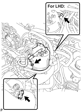
Using a "torx" socket wrench, remove the screw.
-
For LHD:
-
Disconnect the fuel filter warning switch connector.
-
-
Disconnect the fuel heater connector and remove the fuel filter.
-
-
DISCONNECT WIRE HARNESS
-
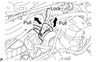
Pull up the lock and disconnect the connector.
-

Disconnect the injector connectors.
-
-
REMOVE FUEL FILTER BRACKET
-
Using a "torx" socket wrench, remove the screw.
-
Remove the 2 bolts and the fuel filter bracket.
-
-
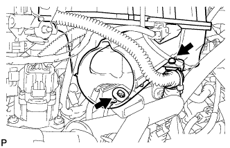
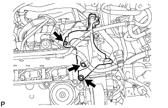
REMOVE INTAKE AIR RESONATOR
-
Disconnect and remove the water reservoir tube from the intake air resonator.
-
Disconnect the turbocharger air temperature sensor connector and loosen the clamp.
-
Remove the bolt.
-
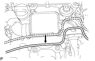
Using a "torx" socket wrench, remove the screw.
-
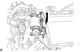
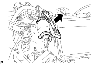
Turn the intake air resonator, and remove the intake air resonator as shown in the illustration.
-
Remove the O-ring from the intake air resonator.
-
-
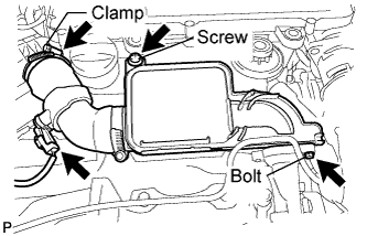
REMOVE THROTTLE VALVE (FOR EGR)
-
Remove the throttle valve connector.
-
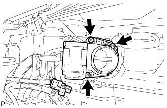
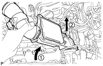
Using a "torx" socket wrench, remove the 3 screws and the throttle valve.
-
Remove the O-ring from the throttle valve.
-
-
REMOVE WIRE HARNESS CLAMP BRACKET
-
Separate the wire harness clamp.
-
Remove the bolt and wire harness clamp bracket.
-
-
DISCONNECT HEATER HOSE
-
Remove the hose clip.
-
Disconnect the heater hose.
-
-
DISCONNECT WATER BY-PASS HOSE
-
Remove the hose clamp.
-
Disconnect the EGR cooler water by-pass hose.
-
-
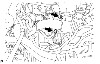
DISCONNECT WATER HOSE
-
Check for dirt in the pipe around the connector before disconnecting. Clean away the dirt as necessary.
-
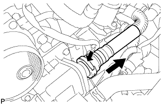
Be sure to disconnect the connectors by hand.
-
When the connector and the pipe are stuck, pinch the fuel pipe with the fingers, and push and pull the connector. Disconnect and pull the connector out of the pipe. Do not use any tools.
-
Check for dirt or other foreign objects on the surface of the seal on the disconnected pipe and clean as necessary.
-
-
DISCONNECT ECM CONNECTOR
-
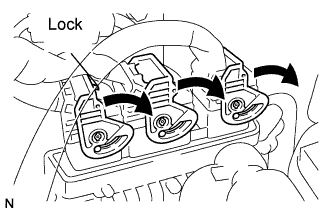
Press the lock and turn the retainers as shown in the illustration.
Note
-
Check the ECM and the area around the ECM for water or dirt. Clean them as necessary.
-
Check the connection of the removed ECM connector for water or dirt. Clean it as necessary.
-
-
Disconnect the 3 ECM connectors.
-
-
REMOVE EGR VALVE ASSEMBLY W/ EGR COOLER
-
Disconnect the EGR valve connector.
-
Using a "torx" socket wrench, remove the 2 screws.
-
Remove the 2 bolts and EGR valve assembly w/ EGR cooler.
-
Remove the EGR valve gasket from the cylinder head.
-
-
REMOVE RADIATOR RESERVOIR TANK ASSEMBLY
-
Remove the 2 clips and disconnect the 2 water by-pass hoses from the reserve tank.
-
Remove the clip and disconnect the water by-pass hose No.5.
-
Remove the bolt and radiator reserve tank.
-
-
SEPARATE WIRE HARNESS AND CONNECTOR
-
Disconnect the camshaft position sensor connector.
-
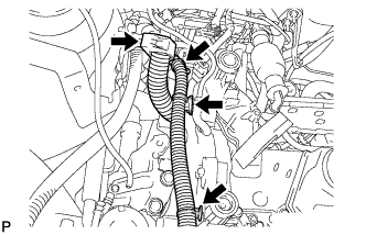
Separate the 4 clamps of the wire harness.
-
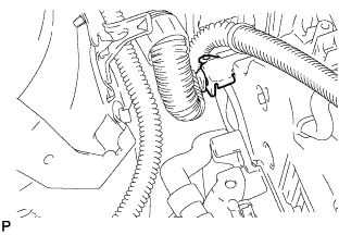
Separate the clamp of the wire harness.
-
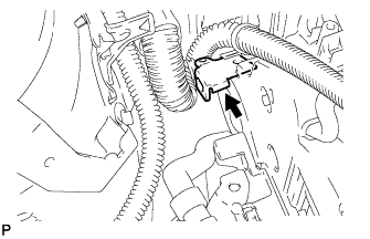
Remove the wire harness clamp.
-
-
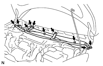
REMOVE TIMING BELT UPPER COVER
-
Remove the 5 bolts and the timing belt cover sub-assembly.
-
-
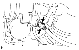
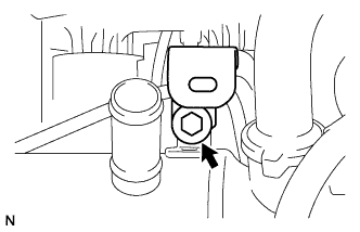
SEPARATE FUEL TEMPERATURE SENSOR
-
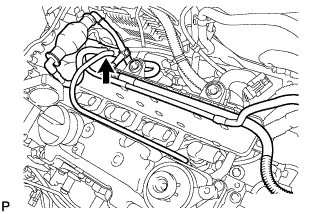
Disconnect the tube and separate the fuel temperature sensor from the cylinder head cover sub-assembly.
-
-
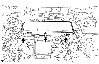
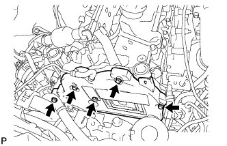
REMOVE CYLINDER HEAD COVER SUB-ASSEMBLY
-
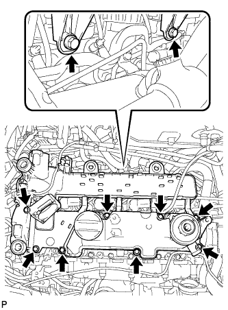
Remove the 10 bolts and the cylinder head cover sub-assembly and gasket.
-
Remove the 4 O-rings from the cylinder head cover sub-assembly.
-
-
REMOVE INJECTION PIPE
Note
-
After removing the fuel pipe, cover the outlets on the common rail with tape to keep out foreign matter.
-
After removing the pipe, put it in a plastic bag to prevent foreign matter from entering the injector inlet.
-
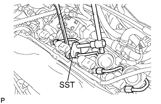
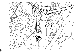
Using SST, loosen the 4 union nuts (injector end).
- SST
- 09023-38401
Note
While holding the union on each injector using a wrench, loosen the union nut on the injection pipe.
-
Using SST, loosen the union nut (supply pump end).
- SST
- 09023-38401
Note
While holding the union on supply pump using a wrench, loosen the union nut on the injection pipe.
-
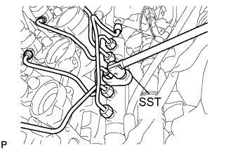
Using SST, loosen the 5 union nuts (common rail side) and remove the injection pipes.
- SST
- 09023-12701
-
-
REMOVE COMMON RAIL ASSEMBLY
-
Remove the bolt and separate the water outlet box support.
-
Disconnect the fuel pressure sensor connector.
-
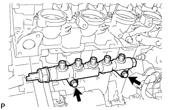
Remove the 2 bolts and common rail assembly from the cylinder block.
-