FUEL SUPPLY PUMP INSTALLATION

-
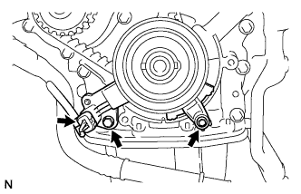
INSTALL FUEL SUPPLY PUMP ASSEMBLY
-
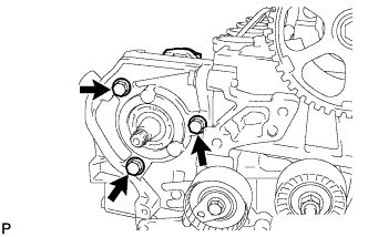
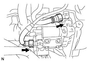
Install the supply pump assembly with the 3 bolts.
- Torque:
- 23 N*m { 235 kgf*cm, 17 ft.*lbf }
-
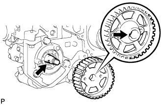
Align the projection on the drive shaft with the groove of the supply pump gear.
-
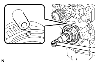
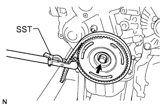
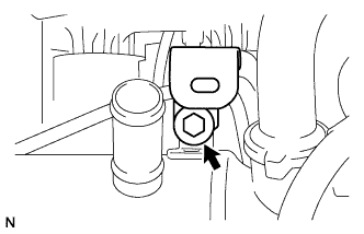
Using SST, install the supply pump gear with the nut.
- SST
- 09960-10010 ( 09962-01000 )
- Torque:
- 50 N*m { 510 kgf*cm, 37 ft.*lbf }
-
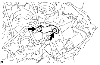
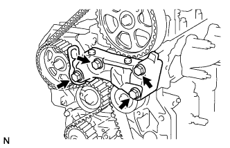
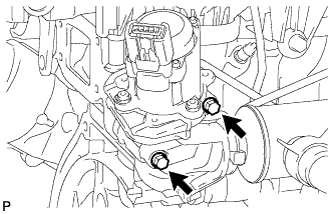
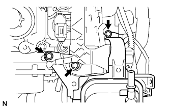
Install the bracket with the 2 bolts and nut.
- Torque:
- 10 N*m { 102 kgf*cm, 7 ft.*lbf }
-
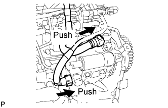
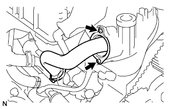
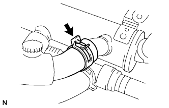
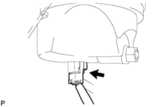
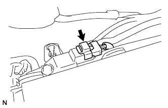
Push the 2 tube connectors into the 2 pipes until the tube connectors make a "click" sound.
Note
-
Before installing the pipe, make sure that it is not damaged. Make sure that there is no dirt present on the connecting surfaces.
-
After connecting, check that the fuel tube connector and the pipe are securely connected by pulling on them.
-
-
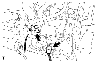
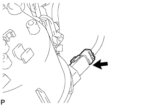
Connect the connector.
-
Temporarily install a new injection pipe.
Note
-
Keep the joints of the injection pipes clean.
-
Screw on by hand, to the end of the thread, the unions of the injection pipes on the supply pump side and on the common rail side.
-
-
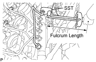
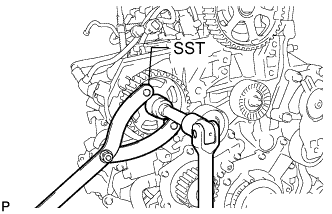
Using SST, tighten the injection pipe with the union nuts.
- SST
- 09023-38401
- Torque:
- When using SST
- 17 N*m { 173 kgf*cm, 13 ft.*lbf }
- When not using SST
- 19 N*m { 194 kgf*cm, 14 ft.*lbf }
Tech Tips
-
Use a torque wrench with a fulcrum length of 300 mm (11.81 in.) (supply pump end).
-
Use a torque wrench with a fulcrum length of 345 mm (13.58 in.) (common rail end).
-
Using SST, retighten the injection pipe with the union nuts.
- SST
- 09023-38401
- Torque:
- When using SST
- 23 N*m { 232 kgf*cm, 17 ft.*lbf }
- When not using SST
- 25 N*m { 255 kgf*cm, 18 ft.*lbf }
Tech Tips
-
Use a torque wrench with a fulcrum length of 300 mm (11.81 in.) (supply pump end).
-
Use a torque wrench with a fulcrum length of 345 mm (13.58 in.) (common rail end).
-
-
SET TIMING MARK
-
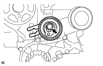
Using SST, set the pulley of the camshaft so that the timing holes of the camshaft drive pulley and the cylinder head are aligned.
- SST
- 09960-10010 ( 09962-01000, 09963-01000 )
-
Using the crankshaft pulley bolt, turn the crankshaft so that the timing holes of the crankshaft timing pulley and the oil pump are aligned.
-
-
INSTALL TIMING BELT
-
Temporarily install the timing belt tensioner with the bolt.
-
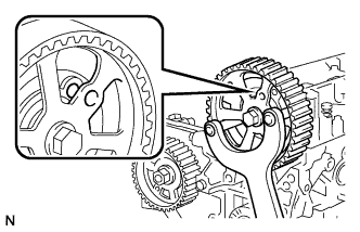
Install the timing belt.
-
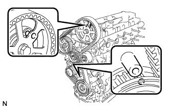
Check that the timing holes are aligned as shown in the illustration.
-
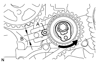
Using a hexagon socket wrench, turn the timing belt tensioner as shown in the illustration.
Tech Tips
Part A should be positioned within area B.
-
Tighten the timing belt tensioner bolt.
- Torque:
- 30 N*m { 306 kgf*cm, 22 ft.*lbf }
-
-
CHECK VALVE TIMING
-
Slowly turn the crankshaft 2 complete revolutions (720°).
-
Check that the timing holes are aligned as shown in the illustration.
-
Remove the crankshaft pulley bolt.
-
-
INSTALL CRANK POSITION SENSOR
-
Install the crankshaft timing pulley support with the bolt.
- Torque:
- 5.0 N*m { 51 kgf*cm, 44 in.*lbf }
-
Install the crankshaft position sensor with the bolt.
- Torque:
- 5.0 N*m { 51 kgf*cm, 44 in.*lbf }
-
Connect the crankshaft position sensor connector.
-
-
INSTALL ENGINE MOUNT BRACKET
-
Install the engine mount bracket with the 4 bolts.
- Torque:
- 55 N*m { 561 kgf*cm, 41 ft.*lbf }
-
-
INSTALL TIMING BELT LOWER COVER
-
Install the timing belt lower cover with the 5 bolts.
- Torque:
- 5.0 N*m { 51 kgf*cm, 44 in.*lbf }
-
-
INSTALL CRANKSHAFT PULLEY
-
Temporarily install the timing belt tensioner with the bolt.
-
Using SST, hold the crankshaft pulley.
- SST
- 09330-00021
-
Tighten the bolt.
- Torque:
- 35 N*m { 357 kgf*cm, 26 ft.*lbf }
-
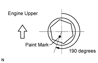
Mark the top surface of the crankshaft pulley bolt with paint.
-
Retighten the bolt by an additional 190 degrees as shown in the illustration.
-
-
INSTALL V-RIBBED BELT TENSIONER SUB-ASSEMBLY
-
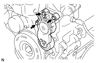
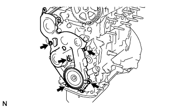
Install the V-ribbed belt tensioner sub-assembly with the 3 bolts.
- Torque:
- 20 N*m { 204 kgf*cm, 15 ft.*lbf }
-
-
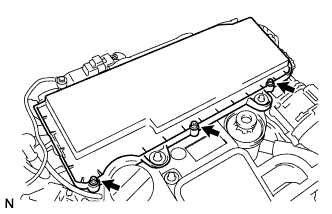
INSTALL CYLINDER HEAD COVER SUB-ASSEMBLY
-
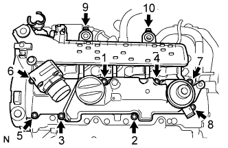
Install 4 new O-rings and a gasket to the cylinder head cover.
-
Temporarily install the cylinder head cover with the 10 bolts.
-
Tighten the 10 bolts in the order shown in the illustration.
- Torque:
- 10 N*m { 102 kgf*cm, 7 ft.*lbf }
-
Connect the diesel throttle valve connector.
-
-
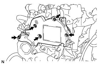
INSTALL EGR VALVE ASSEMBLY
-
Install a new O-ring to the EGR pipe.
-
Temporarily install the EGR valve assembly and gasket with the 2 screws and 2 bolts.
-
Install the clamp with the bolt.
- Torque:
- 6.0 N*m { 61 kgf*cm, 53 in.*lbf }
-
Tighten the 2 bolts.
- Torque:
- 10 N*m { 102 kgf*cm, 7 ft.*lbf }
-
Using a "torx" socket wrench, tighten the 2 screws.
- Torque:
- 5.0 N*m { 51 kgf*cm, 44 in.*lbf }
-
-
INSTALL EGR COOLER WATER BY-PASS HOSE
-
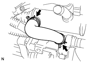
Using pliers, slide the 2 clips to install the water by-pass hose.
-
-
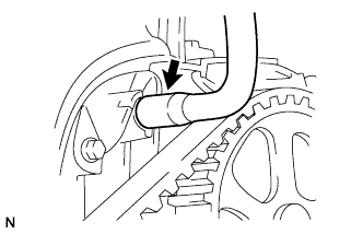
INSTALL HEATER WATER OUTLET HOSE A
-
Using pliers, slide the clip to install the heater water outlet hose A.
-
-
CONNECT ENGINE WIRE NO.2
-
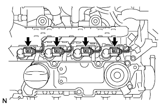
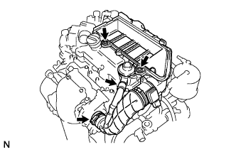
Install the engine wire No.2 to the injector.
CAUTION:
Be sure to connect the injector connectors correctly to prevent malfunctions in the injector.
-
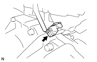
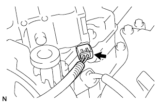
Connect the fuel pressure sensor connector.
-
Connect the glow harness connector.
-
-
INSTALL FUEL FILTER ASSEMBLY
-
Temporarily install the fuel filter assembly with the 2 bolts and screw.
-
Tighten the 2 bolts.
- Torque:
- 10 N*m { 102 kgf*cm, 7 ft.*lbf }
-
Using a "torx" socket wrench, tighten the screw.
- Torque:
- 5.0 N*m { 51 kgf*cm, 44 in.*lbf }
-
Connect the fuel heater connector.
-
Connect the fuel level warning switch connector.
-
Align the connector with the pipe, then push in the connector to the pipe until it makes a "click" sound to connect the fuel return hose to the fuel pump return pipe.
-
Align the connector with the pipe, then push in the connector to the pipe until it makes a "click" sound to connect the fuel hose to the fuel pump pipe.
-
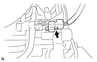
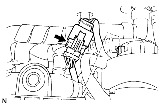
Connect the pressure control valve connector.
-
Connect the fuel return hose to the No.4 injector.
-
-
INSTALL AIR CLEANER CASE SUB-ASSEMBLY
-
Temporarily install the air cleaner case, air hose No.1 clamp and 2 screws.
-
Using a "torx" socket wrench, tighten the 2 screws.
- Torque:
- 5.0 N*m { 51 kgf*cm, 44 in.*lbf }
-
Tighten the air hose No.1 clamp.
- Torque:
- 5.0 N*m { 51 kgf*cm, 44 in.*lbf }
-
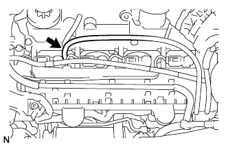
Connect the PCV hose.
-
-
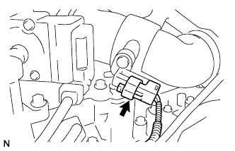
INSTALL TURBO PRESSURE SENSOR
-
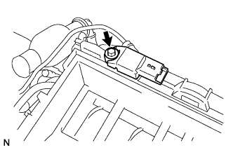
Install the turbo pressure sensor with the bolt.
- Torque:
- 4.0 N*m { 41 kgf*cm, 35 in.*lbf }
-
Connect the turbo pressure sensor connector.
-
Connect the turbo pressure sensor to the cylinder head cover.
-
-
INSTALL INTAKE AIR RESONATOR SUB-ASSEMBLY
-
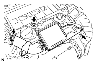
Install a new O-ring to the intake air resonator.
-
Temporarily install the intake air resonator with the clamp, bolt and screw.
-
Tighten the bolt.
- Torque:
- 7.5 N*m { 77 kgf*cm, 66 in.*lbf }
-
Tighten the air hose No.1 clamp.
- Torque:
- 3.5 N*m { 36 kgf*cm, 31 in.*lbf }
-
Using a "torx" socket wrench, tighten the screw.
- Torque:
- 7.5 N*m { 77 kgf*cm, 66 in.*lbf }
-
Connect the air temperature sensor connector.
-
-
INSTALL AIR CLEANER CAP SUB-ASSEMBLY
-
Install the air filter element.
-
Using a "torx" socket wrench, install the air cleaner case sub-assembly with the 3 screws.
- Torque:
- 5.0 N*m { 51 kgf*cm, 44 in.*lbf }
-
-
INSTALL TIMING BELT UPPER COVER
-
Install the timing belt upper cover with the 5 bolts.
- Torque:
- 5.0 N*m { 51 kgf*cm, 44 in.*lbf }
-
-
INSTALL ENGINE W/ TRANSAXLE