FUEL SUPPLY PUMP REMOVAL

-
REMOVE ENGINE W/ TRANSAXLE
-
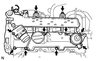
REMOVE TIMING BELT UPPER COVER
-
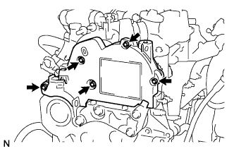
Remove the 5 bolts and timing belt upper cover.
-
-
REMOVE AIR CLEANER CAP SUB-ASSEMBLY
-
Using a "torx" socket wrench, remove the 3 screws.
-
Remove the air cleaner cap sub-assembly.
-
Remove the air filter element.
-
-
REMOVE INTAKE AIR RESONATOR SUB-ASSEMBLY
-
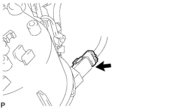
Disconnect the intake air temperature sensor connector.
-
Loosen the air hose No.2 clamp.
-
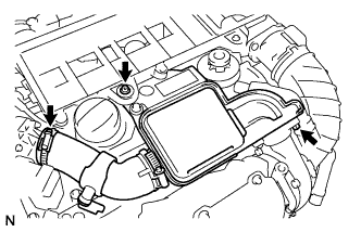
Using a "torx" socket wrench, remove the screw.
-
Remove the bolt, intake air resonator and O-ring.
-
-
REMOVE TURBO PRESSURE SENSOR
-
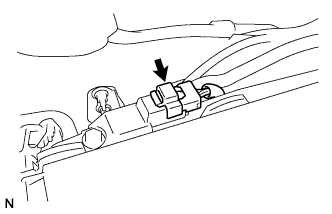
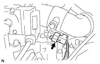
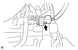
Disconnect the turbo pressure sensor connector.
-
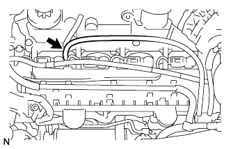
Disconnect the turbo pressure sensor hose from the cylinder head cover.
-
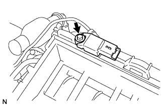
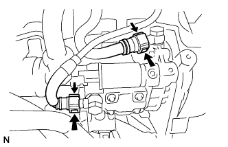
Remove the bolt and turbo pressure sensor.
-
-
REMOVE AIR CLEANER CASE SUB-ASSEMBLY
-
Loosen the air hose No.1 clamp.
-
Disconnect the PCV hose from the cylinder head cover.
-
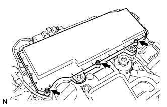
Using a "torx" socket wrench, remove the 2 screws.
-
Remove the air cleaner case sub-assembly.
-
-
REMOVE FUEL FILTER ASSEMBLY
-
Disconnect the fuel return hose from the No.4 injector.
-
Disconnect the fuel temperature sensor connector.
-
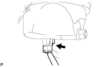
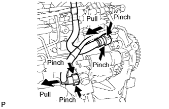
Pinch the retainer as illustrated, then pull out the fuel hose from the fuel pump.
-
Pinch the retainer as illustrated, then pull out the fuel return hose from the fuel pump.
-
Disconnect the fuel level warning switch connector.
-
Disconnect the fuel heater hose connector (w/ fuel heater).
-
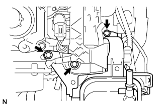
Using a "torx" socket wrench, remove the screw.
-
Remove the 2 bolts, fuel filter, and fuel bracket with priming pump.
-
-
DISCONNECT ENGINE WIRE NO.2
-
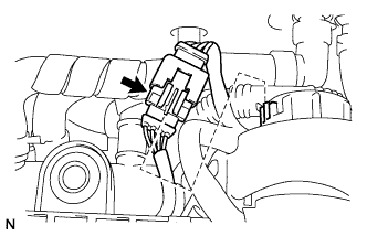
Disconnect the glow harness connector.
-
Disconnect the fuel pressure sensor connector.
-
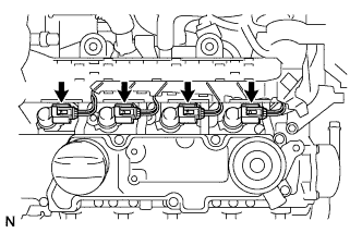
Disconnect the 4 injector connectors and remove the engine wire No.2.
-
-
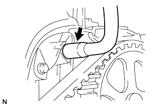
REMOVE HEATER WATER OUTLET HOSE A
-
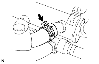
Using pliers, slide the clip to remove the heater water outlet hose A.
-
-
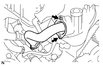
REMOVE EGR COOLER WATER BY-PASS HOSE
-
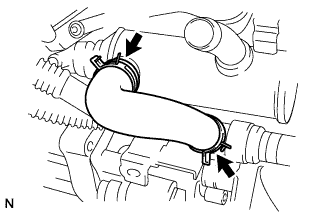
Using pliers, grip the claws of the 2 clips and slide the 2 clips to remove the water by-pass hose.
-
-
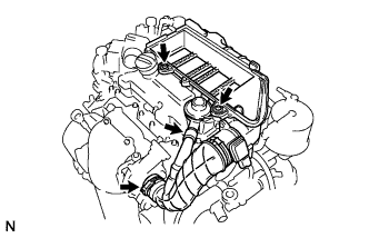
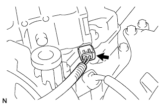
REMOVE EGR VALVE ASSEMBLY
-
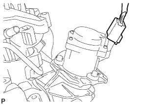
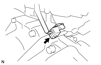
Disconnect the EGR valve connector.
-
Using a "torx" socket wrench, remove the 2 screws.
-
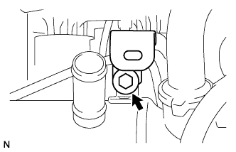
Remove the bolt and clamp from the EGR pipe.
-
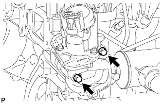
Remove the 2 bolts from the EGR valve.
-
Remove the EGR valve assembly, gasket and O-ring.
-
-
REMOVE CYLINDER HEAD COVER SUB-ASSEMBLY
-
Disconnect the diesel throttle valve connector.
-
Remove the 10 bolts, cylinder head cover sub-assembly, gasket and 4 O-rings.
-
-
REMOVE V-RIBBED BELT TENSIONER SUB-ASSEMBLY
-
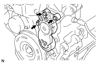
Remove the 3 bolts and V-ribbed belt tensioner sub-assembly.
-
-
REMOVE CRANKSHAFT PULLEY
-
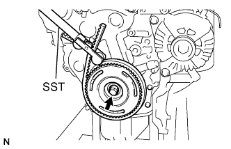
Using SST, hold the crankshaft pulley.
- SST
- 09330-00021
-
Remove the bolt and crankshaft pulley.
-
-
REMOVE TIMING BELT LOWER COVER
-
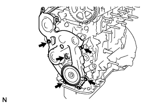
Remove the 5 bolts and timing belt lower cover.
-
-
REMOVE ENGINE MOUNT BRACKET
-
Remove the 4 bolts and engine mount bracket.
-
-
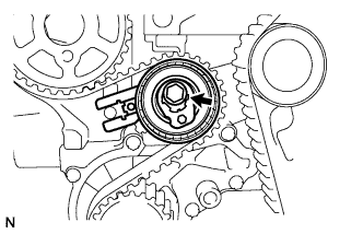
SET TIMING MARK
-
Using the crankshaft pulley bolt, turn the crankshaft so that the timing holes of the crankshaft timing pulley and the oil pump are aligned.
-
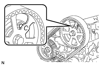
Check that the timing holes of the camshaft drive pulley and the cylinder head are aligned.
-
-
REMOVE CRANK POSITION SENSOR
-
Disconnect the crank position sensor connector.
-
Remove the bolt and crank position sensor.
-
Remove the bolt and crankshaft timing pulley support.
-
-
REMOVE TIMING BELT
-
Remove the bolt and timing belt tensioner.
-
Remove the timing belt.
-
-
REMOVE FUEL SUPPLY PUMP ASSEMBLY
-
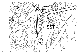
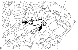
Using SST, loosen the union nuts and remove the injection pipe.
- SST
- 09023-38401
- 09023-12701
Note
While holding the union on supply pump using a wrench, loosen the union nut on the injection pipe.
-
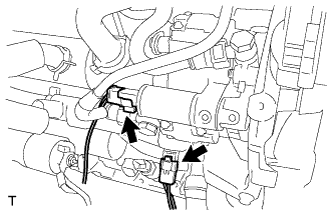
Disconnect the 2 connectors.
-
Pinch the tube connectors and then pull out the fuel tubes.
Note
-
Check if there is any dirt around the connectors before this operation and remove the dirt as necessary.
-
Remove the quick connectors by hand.
-
Do not damage the disconnected pipe and connector. Prevent intrusion of foreign objects by covering them with plastic bags.
-
If the pipe and the connector are stuck, try wiggling or pushing and pulling the connector to release it. Pull the connector off of the pipe carefully.
-
-
Remove the 2 bolts, nut, and bracket.
-
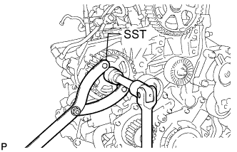
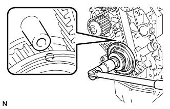
Using SST, loosen the nut.
- SST
- 09960-10010 ( 09962-01000 )
-
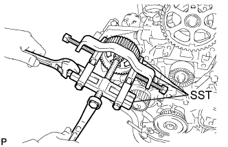
Using SST, separate the supply pump gear.
- SST
- 09950-40011 ( 09951-04010, 09952-04010, 09953-04010, 09954-04010, 09955-04061 )
-
Remove the nut and supply pump gear.
-
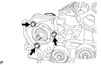
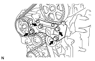
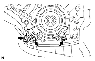
Remove the 3 bolts and supply pump assembly.
-