VALVE CLEARANCE ADJUSTMENT

-
DISCONNECT CABLE FROM NEGATIVE BATTERY TERMINAL
-
REMOVE AIR CLEANER CAP SUB-ASSEMBLY
-
Remove the air cleaner cap sub-assembly Click here.
-
-
DISCONNECT FUEL VAPOR FEED HOSE NO.1 AND NO.2
-
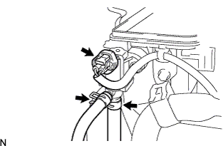
Disconnect the fuel vapor feed hose No.1 and No.2.
-
Disconnect the VSV connector.
-
-
REMOVE IGNITION COIL NO.1
-
Remove the ignition coil No.1 Click here.
-
-
REMOVE CYLINDER HEAD COVER SUB-ASSEMBLY
-
Remove the cylinder head cover sub-assembly Click here.
-
-
SET NO.1 CYLINDER TO TDC/EXHAUST
-
Turn the crankshaft clockwise to align the timing mark on the crankshaft pulley and the indicator on the timing chain cover.
-
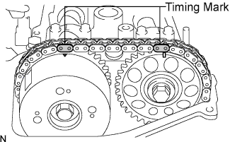
Check that the matchmarks on the top of the camshaft timing sprockets to the camshaft align.
Tech Tips
If the matchmarks do not align, turn the crankshaft clockwise one complete revolution and then check that they align.
-
-
INSPECT VALVE CLEARANCE
-
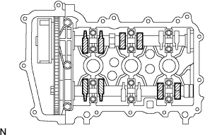
Check only the valves indicated.
-
Using a feeler gauge, measure the clearance between the valve lifter and camshaft.
Valve clearance (Cold) for intake 0.145 to 0.235 mm (0.00571 to 0.00925 in.) for exhaust 0.275 to 0.365 mm (0.01083 to 0.01437 in.) Tech Tips
Be sure to insert the feeler gauge from the spark plug side (center).
-
Record the out-of-specification valve clearance measurements. They will be used later to determine the required replacement valve lifters.
-
-
Turn the crankshaft 1 revolution (360°).
-
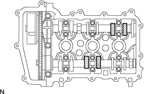
Check only the valves indicated.
-
Using a feeler gauge, measure the clearance between the valve lifter and camshaft.
Valve clearance(Cold) for intake 0.145 to 0.235 mm (0.00571 to 0.00925 in.) for exhaust 0.275 to 0.365 mm (0.01083 to 0.01437 in.) Tech Tips
Be sure to insert the feeler gauge from the spark plug side (center).
-
Record the out-of-specification valve clearance measurements. They will be used later to determine the required replacement valve lifters.
-
-
-
ADJUST VALVE CLEARANCE
-
Remove the No.1, No.2 camshafts Click here.
-
Remove the valve lifters Click here.
-
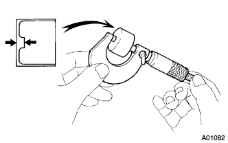
Using a micrometer, measure the thickness of the removed valve lifters.
-
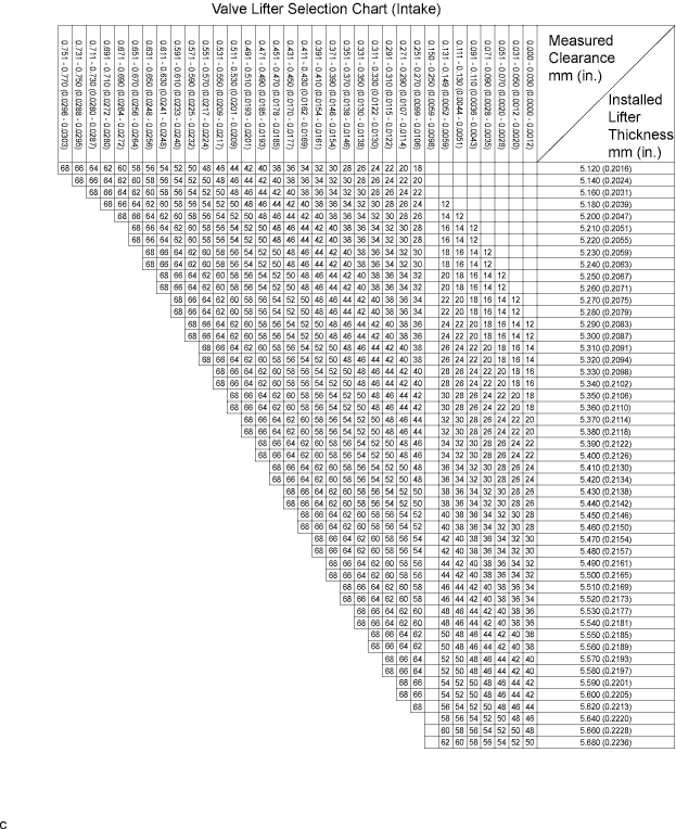
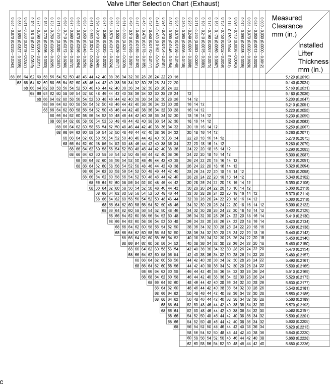
Calculate the thickness of a new lifter so that the valve clearance comes within the specified value.
A Thickness of new lifter B Thickness of used lifter C Measured valve clearance Valve clearance Intake A = B + (C - 0.18 mm (0.0071 in.)) Exhaust A = B + (C - 0.31 mm (0.0122 in.)) Example (Intake):
Measured Intake valve clearance = 0.38 mm (0.0150 in.)
0.38 mm (0.0150 in.) - 0.18 mm (0.0071 in.) = 0.20 mm (0.0079 in.)
(Measured - Specification = Excess clearance)
Used lifter measurement = 5.25 mm (0.2067 in.)
0.20 mm (0.0079 in.) + 5.25 mm (0.2067 in.) = 5.45 mm (0.2146 in.)
(Excess clearance + Used lifter = Ideal new lifter)
Closest new lifter = 5.46 mm (0.2150 in.)
Select No.46 lifter
Tech Tips
-
Select a new lifter with a thickness as close to the calculated values as possible.
-
Lifter are available in 29 sizes in increments of 0.020 mm (0.0008 in.), from 5.12 mm (0.2016 in.) to 5.68 mm (0.2236 in.).
-
Refer to the New Lifter Thickness Table on the next 2 pages.
-
-
Install the valve lifters Click here.
-
Install the No.1, No.2 camshafts Click here.
Tech Tips
New lifter thickness mm (in.) Lifter No. Thickness Lifter No. Thickness Lifter No. Thickness 12 5.12 (0.2016) 32 5.32 (0.2094) 52 5.52 (0.2173) 14 5.14 (0.2024) 34 5.34 (0.2102) 54 5.54 (0.2181) 16 5.16 (0.2031) 36 5.36 (0.2110) 56 5.56 (0.2189) 18 5.18 (0.2039) 38 5.38 (0.2118) 58 5.58 (0.2197) 20 5.20 (0.2047) 40 5.40 (0.2126) 60 5.60 (0.2205) 22 5.22 (0.2055) 42 5.42 (0.2134) 62 5.62 (0.2213) 24 5.24 (0.2063) 44 5.44 (0.2142) 64 5.64 (0.2220) 26 5.26 (0.2071) 46 5.46 (0.2150) 66 5.66 (0.2228) 28 5.28 (0.2079) 48 5.48 (0.2157) 68 5.68 (0.2236) 30 5.30 (0.2087) 50 5.50 (0.2165) - -
-
-
INSTALL CYLINDER HEAD COVER SUB-ASSEMBLY
-
Install the cylinder head cover sub-assembly Click here.
-
-
INSTALL IGNITION COIL NO.1
-
Install the ignition coil No.1 Click here.
-
-
CONNECT FUEL VAPOR FEED HOSE NO.1 AND NO.2
-
Connect the VSV connector.
-
Connect the fuel vapor feed hose No.1 and No.2.
-
-
CONNECT CABLE TO NEGATIVE BATTERY TERMINAL
- Torque:
- 5.4 N*m { 55 kgf*cm, 48 in.*lbf }
-
INSPECT ENGINE OIL LEAKS
-
INSTALL AIR CLEANER CAP SUB-ASSEMBLY
-
Install the air cleaner cap sub-assembly Click here.
-