ENGINE ON-VEHICLE INSPECTION

-
INSPECT ENGINE COOLANT
-
Inspect the engine coolant Click here.
-
-
INSPECT ENGINE OIL
-
Inspect the engine oil Click here.
-
-
INSPECT BATTERY
-
Inspect the battery Click here.
-
-
INSPECT AIR CLEANER FILTER ELEMENT SUB-ASSEMBLY
-
Remove the air cleaner filter element from the cylinder head cover sub-assembly.
-
Visually check that there is no dirt, clog, and/or damage to the air cleaner filter element.
Tech Tips
-
If there is any dirt or a clog on the air cleaner filter element, clean it with compressed air.
-
If any dirt or a clog remains even after cleaning the air cleaner filter element with compressed air, replace it.
-
-
-
INSPECT SPARK PLUG
-
Inspect the spark plug Click here.
-
-
INSPECT IGNITION TIMING
Note
-
Turn all the electrical system and the A/C off.
-
Inspect the ignition timing with the cooling fan off.
-
When checking the ignition timing, shift the transmission to the neutral position.
-
Warm up and stop the engine.
-
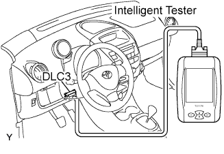
When using the intelligent tester:
-
Connect the intelligent tester to the DLC3.
-
Turn the ignition switch on.
-
Select the item:
Powertrain / Engine and ETC / Active Test / TE1 (TC) / ON.
Tech Tips
Refer to the intelligent tester operator's manual if you need help to select Active Test.
-
Inspect the ignition timing at idle.
Ignition timing 8 to 12 degrees BTDC -
Select the item:
TE1 (TC) / OFF
-
Turn the ignition switch off.
-
Disconnect the intelligent tester from the DLC3.
-
-
When not using the intelligent tester:
-
Remove the air cleaner cap sub-assembly Click here.
-
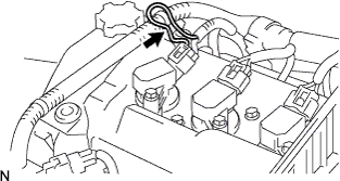
Install the tester terminal of a timing light to the position shown in the illustration.
Note
-
Use a timing light that detects the first signal.
-
After checking, be sure to wrap the wire harness with tape.
-
-
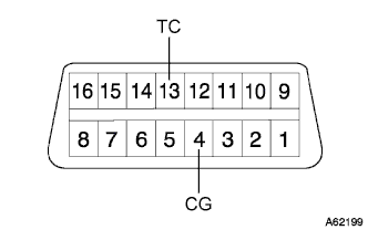
Using SST, connect terminals 13 (TC) and 4 (CG) of the DLC3.
- SST
- 09843-18040
Note
Make sure of the terminal numbers before connecting them. Connecting the wrong terminals can damage the engine.
-
Turn the ignition switch on.
-
Inspect the ignition timing at idle.
Ignition timing 8 to 12 degrees BTDC Tech Tips
Run the engine speed at 1,000 to 1,300 rpm for 5 seconds, then check that the engine speed returns to the idle speed.
-
Disconnect terminals 13 (TC) and 4 (CG) of the DLC3.
-
Turn the ignition switch off.
-
Remove the timing light.
-
Install the air cleaner cap sub-assembly Click here.
-
-
-
INSPECT ENGINE IDLE SPEED
Note
-
Turn all the electrical system and the A/C OFF.
-
Inspect the engine idle speed with the cooling fan OFF.
-
When checking the idle speed, shift the transmission to the neutral position.
-
Warm up and stop the engine.
-

When using the intelligent tester:
-
Connect the intelligent tester to the DLC3.
-
Turn the ignition switch on.
-
Select the item:
Powertrain / Engine and ECT / Data List / Engine SPD.
Tech Tips
Refer to the intelligent tester operator's manual if you need help to select Data List.
-
Inspect the engine idle speed.
Idle speed 790 to 890 rpm -
Turn the ignition switch off.
-
Disconnect the intelligent tester from the DLC3.
-
-
When not using the intelligent tester:
-
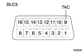
Install SST to terminal 9 (TAC) of the DLC3, then connect a tachometer.
- SST
- 09843-18040
Note
Make sure of the terminal numbers before connecting them. Connecting the wrong terminals can damage the engine.
-
Turn the ignition switch on.
-
Inspect the engine idling speed.
Idle speed 790 to 890 rpm -
Turn the ignition switch off.
-
Disconnect a tachometer.
-
Remove SST from terminal 9 (TAC).
-
-
-
INSPECT COMPRESSION
-
Warm up and stop the engine.
-
Remove the air cleaner cap sub-assembly Click here.
-
Remove the 3 ignition coils Click here.
-
Remove the 3 spark plugs.
-
Disconnect the 3 fuel injector connectors.
-
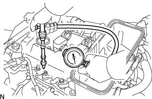
Inspect cylinder compression pressure.
-
Insert a compression gauge into the spark plug hole.
-
Fully open the throttle.
-
While cranking the engine, measure the compression pressure.
Compression pressure (Normal condition) 1,422 kPa (14.5 kgf/cm2, 206 psi) Minimum pressure 1,079 kPa (11.0 kgf/cm2, 156 psi) Difference between each cylinder 147 kPa (1.5 kgf/cm2, 21 psi) or less Note
-
Use a fully-charged battery so the engine speed can be increased to 400 rpm or more.
-
Inspect the other cylinders in the same way.
-
Measure the compression as quickly as possible.
-
-
If the cylinder compression is low, pour a light coat of engine oil into the cylinder through the spark plug hole, then inspect it again.
Tech Tips
-
If adding oil increases the compression, the piston rings and/or cylinder bore may be worn or damaged.
-
If pressure stays low, the valve may be stuck or seated improperly, or there may be leakage from the gasket.
-
-
-
Connect the 3 fuel injector connectors.
-
Install the 3 spark plugs.
- Torque:
- 25 N*m { 255 kgf*cm, 18 ft.*lbf }
-
Install the 3 ignition coils Click here.
-
Install the air cleaner cap sub-assembly Click here.
-
-
INSPECT CO/HC
Tech Tips
The ECM properly controls the CO/HC concentration in the emission gas.
-
Start the engine.
-
Run the engine at 2,500 rpm for approximately 180 seconds.
-
Insert the CO/HC meter testing probe at least 40 cm (1.3 ft) into the tailpipe while idling.
-
Check the CO/HC concentration at idle.
Standard CO concentration 0.2% or less HC concentration 70 ppm or less If the CO/HC concentration does not comply with the regulations, troubleshoot in the order given below.
-
Check the heated oxygen sensor operation Click here.
-
See the table below for possible causes, then inspect the applicable causes and repair them if necessary.
CO HC Problems Causes Normal High Rough idle
-
Faulty ignitions:
-Fouled, shorted or improperly gapped plugs
-
Incorrect valve clearance
-
Leaks in intake and exhaust valves
-
Leaks in cylinders
Low High Rough Idle
(Fluctuating HC reading)
-
Lean mixture causing misfire
-
Faulty SFI systems:
-Faulty pressure regulator
-Defective engine coolant temperature sensor
-Detective mass air flow meter
-Faulty ECM
-Faulty injectors
-Faulty throttle body
High High Rough idle
(Black smoke from exhaust)
-
Faulty SFI systems:
-Faulty pressure regulator
-Defective engine coolant temperature sensor
-Detective mass air flow meter
-Faulty ECM
-Faulty injectors
-Faulty throttle body
-
-