ECD SYSTEM, Diagnostic DTC:P2141, P2142

| DTC Code | DTC Name |
|---|---|
| P2141 | Open or Short to GND in EGR Throttle Circuit |
| P2142 | Short to B+ in EGR Throttle Circuit |
DESCRIPTION
-
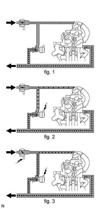
The ECM adjusts the opening angle of the EGR valve and throttle valve (for EGR) to control the EGR (Exhaust Gas Recirculation) amount to reduce emissions.
-
When the throttle valve (for EGR) opening angle becomes smaller, the pressure in the intake manifold drops. This improves the flow of exhaust gas to the intake manifold. (fig. 3)
-
The throttle valve (for EGR) does not have a position sensor.
| DTC No. | DTC Detection Condition | Trouble Area | Possible to Detect | |
|---|---|---|---|---|
| Ignition Switch | Engine Run | |||
| P2141 | Open or short in throttle valve (for EGR) circuit for 2 sec. or more (1 trip detection logic) |
|
- | ON |
| P2142 | Short in throttle valve (for EGR) circuit for 2 sec. or more (1 trip detection logic) |
|
- | ON |
FAIL-SAFE
| DTC No. | Fail-safe Operation | Fail-safe Deactivation Condition |
|---|---|---|
| P2141 | Stops the EGR. | Next engine start. |
| P2142 | - | - |
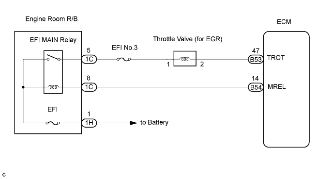
WIRING DIAGRAM
INSPECTION PROCEDURE
Tech Tips
-
If the ECM is replaced, variant coding (variant coding indicates the presence of vehicle accessory items, A/C, etc.) should always be performed Click here.
-
Before removing the ECM and the peripheral parts, wait at least 3 minute after turning the ignition switch off (If the cooling fan is operating, remove the ECM and the peripheral parts after the fan stops.).
PROCEDURE
-
PERFORM ACTIVE TEST BY INTELLIGENT TESTER (THROTTLE VALVE (FOR EGR))
-
Connect the intelligent tester to the DLC3.
-
Turn the ignition switch to the ON position and turn the intelligent tester ON.
-
Clear the DTC Click here.
-
Select the following menu items: Powertrain / Engine and ECT / Active Test / EGR Throttle.
OK Operating sound can be heard from the throttle valve (for EGR).
NG 
INSPECT THROTTLE VALVE (FOR EGR) (VOLTAGE) Click here
OK 
CHECK FOR INTERMITTENT PROBLEMS
-
-
INSPECT THROTTLE VALVE (FOR EGR) (VOLTAGE)
-
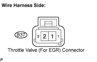
Disconnect the B37 throttle valve (for EGR) connector.
-
Turn the ignition switch to the ON position.
-
Measure the voltage according to the value(s) in the table below.
Standard voltage Tester Connection Specified Condition Throttle valve (for EGR) (B37-1) - Body ground 11 to 14 V
NG
CHECK HARNESS AND CONNECTOR (EFI MAIN RELAY - THROTTLE VALVE (FOR EGR)) Click here
OK 
-
-
INSPECT THROTTLE VALVE (FOR EGR)
-
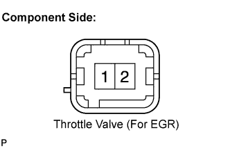
Disconnect the B37 throttle valve (for EGR) connector.
-
Measure the resistance according to the value(s) in the table below.
Standard resistance Tester Connection Specified Condition 1 - 2 5 to 10 Ω
NG 
REPLACE THROTTLE VALVE (FOR EGR)
OK
-
-
CHECK HARNESS AND CONNECTOR (THROTTLE VALVE (FOR EGR) - ECM)
-
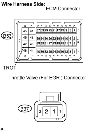
Disconnect the B53 ECM connector.
-
Disconnect the B37 throttle valve (for EGR) connector.
-
Measure the resistance according to the value(s) in the table below.
Standard resistance Check for open Tester Connection Specified Condition TROT (B53-47) - Throttle valve (for EGR) (B37-2) Below 1 Ω Check for short Tester Connection Specified Condition TROT (B53-47) or Throttle valve (for EGR) (B37-2) - Body ground 10 kΩ or higher
NG
REPAIR OR REPLACE HARNESS OR CONNECTOR
OK
REPLACE ECM
-
-
CHECK HARNESS AND CONNECTOR (EFI MAIN RELAY - THROTTLE VALVE (FOR EGR))
-
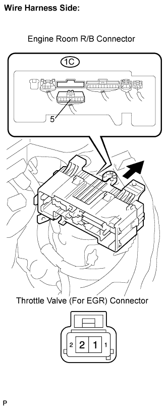
Disconnect the B37 throttle valve (for EGR) connector.
-
Remove the engine room R/B.
-
Remove the engine room R/B lower cover.
-
Disconnect the 1C engine room R/B connector.
-
Measure the resistance according to the value(s) in the table below.
Standard resistance Check for open Tester Connection Specified Condition Throttle valve (for EGR) (B37-1) - Engine room R/B (1C-5) Below 1 Ω Check for short Tester Connection Specified Condition Throttle valve (for EGR) (B37-1) or Engine room R/B (1C-5) - Body ground 10 kΩ or higher
NG
REPAIR OR REPLACE HARNESS OR CONNECTOR
OK
-
-
INSPECT EFI MAIN RELAY (VOLTAGE)
-
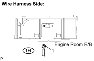
Remove the engine room R/B.
-
Remove the engine room R/B lower cover.
-
Disconnect the 1H engine room R/B connector.
-
Measure the voltage according to the value(s) in the table below.
Standard voltage Tester Connection Specified Condition Engine room R/B (1H-1) - Body ground 11 to 14 V
NG
CHECK AND REPAIR HARNESS AND CONNECTOR (BATTERY - EFI MAIN RELAY)
OK
-
-
CHECK HARNESS AND CONNECTOR (EFI MAIN RELAY - ECM)
-
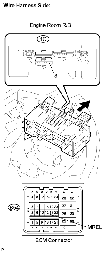
Disconnect the B54 ECM connector.
-
Remove the engine room R/B.
-
Remove the engine room R/B lower cover.
-
Disconnect the 1C engine room R/B connector.
-
Measure the resistance according to the value(s) in the table below.
Standard resistance Check for open Tester Connection Specified Condition MREL (B54-14) - Engine room R/B (1C-8) Below 1 Ω Check for short Tester Connection Specified Condition MREL (B54-14) or Engine room R/B (1C-8) - Body ground 10 kΩ or higher
NG
REPAIR OR REPLACE HARNESS OR CONNECTOR
OK
-
-
REPLACE ENGINE ROOM R/B (EFI MAIN RELAY)
NEXT
-
CHECK IF DTC RECURS (P2141 AND/OR P2142)
-
Connect the intelligent tester to the DLC3.
-
Clear the DTC Click here.
-
Start the engine and turn the intelligent tester on.
-
Select the following menu items: Powertrain / Engine and ECT / DTC.
-
Read the DTCs displayed on the intelligent tester.
Result Display (DTC output) Proceed To No output A P2141 and/or P2142 B
B
REPLACE ECM
A
END
-