ECD SYSTEM, Diagnostic DTC:P1403, P1404

| DTC Code | DTC Name |
|---|---|
| P1403 | Open / Short to B+ or Short to GND in PTC Heater 1 Circuit |
| P1404 | Open / Short to B+ or Short to GND in PTC Heater 2 Circuit |
DESCRIPTION
The PTC heater is equipped on vehicles for use in a cold region.
The function of PTC heater provided by the ECM is used to facilitate heating of the passenger compartment. It consist heating of the passenger compartment.
The ECM sends the additional heating request on the basis of the engine coolant temperature and intake air temperature. To maintain driving comfort and prevent overload applied to the electrical system, the heater elements are controlled at 2 stages with the signals of engine coolant temperature, intake air temperature, engine revolution speed, and alternator.
-
PTC heater capacity:
-
1st step (330 W: No.1)
-
2nd step (660 W: No.1 + No.2)
-
Engine coolant temperature sensor signal:
-
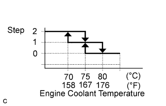
Based on engine coolant temperature, PTC heater requirement step is decided.
-
Engine revolution speed signal:
-
When the head light is turned on and engine revolution speed is decreased, the PTC heater step will go down.
-
Intake air temperature signal:
-
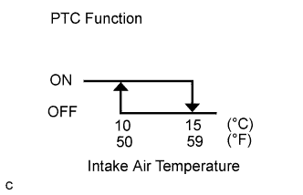
When vehicle speed is less than 15 km/h (9.3 mph), the air temperature value data should be kept at the previous value. When vehicle speed became more than 15 km/h (9.3 mph), new air temperature value can be used.
-
Requirement of idling up:
-
When the PTC heater is operated, engine revolution speed is required to be increased by 120 rpm at idling. (750 rpm (original idle) + 120 rpm = 870 rpm)
| DTC No. | DTC Detection Condition | Trouble Area | Possible to Detect | |
|---|---|---|---|---|
| Ignition Switch | Engine Run | |||
| P1403 | Open or short in PTC heater circuit 1 for 2 sec. or more. |
|
ON | ON |
| P1404 | Open or short in PTC heater circuit 2 for 2 sec. or more. |
|
ON | ON |
FAIL-SAFE
| DTC No. | Fail-safe Operation | Fail-safe Deactivation Condition |
|---|---|---|
| P1403 | - | - |
| P1404 | - | - |
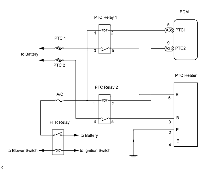
WIRING DIAGRAM
INSPECTION PROCEDURE
Tech Tips
-
If the ECM is replaced, variant coding (variant coding indicates the presence of vehicle accessory items, A/C, etc.) should always be performed Click here.
-
Before removing the ECM and the peripheral parts, wait at least 3 minute after turning the ignition switch off (If the cooling fan is operating, remove the ECM and the peripheral parts after the fan stops.).
PROCEDURE
-
INSPECT PTC HEATER RELAY (VOLTAGE)
-
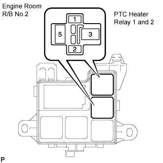
Remove the PTC heater relays 1 and 2 from the engine room R/B No.2.
-
Turn the ignition switch to the ON position.
-
Active the blower motor.
-
Measure the voltage according to the value(s) in the table below.
Standard voltage Tester Connection Specified Condition Engine room R/B No.2 (PTC heater relay 1 terminal 1) - Body ground 11 to 14 V Engine room R/B No.2 (PTC heater relay 1 terminal 3) - Body ground 11 to 14 V Engine room R/B No.2 (PTC heater relay 2 terminal 1) - Body ground 11 to 14 V Engine room R/B No.2 (PTC heater relay 2 terminal 3) - Body ground 11 to 14 V
NG 
CHECK HEATER RELAY. IF OK, CHECK AND REPLACE HARNESS AND CONNECTOR (BATTERY - PTC HEATER RELAY)
OK 
-
-
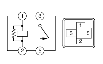
INSPECT PTC HEATER RELAY
-
Remove the PTC heater relays 1 and 2 form the engine room R/B No.2.
-
Measure the resistance according to the value(s) in the table below.
Tester Connection Specified Condition 3 - 5 10 kΩ or higher 3 - 5 Below 1 Ω
(When battery voltage applied to terminals 1 and 2)
NG
REPLACE PTC HEATER RELAY
OK
-
-
CHECK HARNESS AND CONNECTOR (PTC HEATER RELAY - ECM)
-

Disconnect the A35 ECM connector.
-
Remove the PTC heater relays 1 and 2 from the engine room R/B No.2.
-
Measure the resistance according to the value(s) in the table below.
Standard resistance (Check for open) Tester Connection Specified Condition PTC1 (A35-5) - Engine room R/B No.2 (PTC heater relay 1 terminal 2) Below 1 Ω PTC2 (A35-9) - Engine room R/B No.2 (PTC heater relay 2 terminal 2) Below 1 Ω Standard resistance (Check for short) Tester Connection Specified Condition PTC1 (A35-5) or Engine room R/B No.2 (PTC heater relay 1 terminal 2) - Body ground 10 kΩ or higher PTC2 (A35-9) or Engine room R/B No.2 (PTC heater relay 2 terminal 2) - Body ground 10 kΩ or higher
NG
REPAIR OR REPLACE HARNESS OR CONNECTOR
OK
-
-
CHECK IF DTC RECURS (P1403 AND/OR P1404)
-
Connect the intelligent tester to the DLC3.
-
Clear the DTC Click here.
-
Turn the ignition switch to the ON position and intelligent tester on.
-
Select the following menu items: Powertrain / Engine and ECT / DTC.
-
Read the DTCs displayed on the intelligent tester.
Result Display (DTC output) Proceed To No output A DTC P1403 and/or P1404 B
B
REPLACE ECM
A 
END
-