ECD SYSTEM, Diagnostic DTC:P1349, P1350, P1351, P1352

| DTC Code | DTC Name |
|---|---|
| P1349 | Short to B+ in Glow Relay Circuit |
| P1350 | Open or Short to GND in Glow Relay Circuit |
| P1351 | Glow Relay Coherency Test (Open Relay) |
| P1352 | Glow Relay Coherency Test (Latched Relay) |
DESCRIPTION
The glow plugs operate to improve cold engine starting performance, and to prevent a drop in emission control efficiency. The glow plug is controlled by the glow plug relay, which is controlled by the ECM.
-
Pre-heating time
-
Post heating time
-
Lighting of the glow indicator light
-
Function diagnostic (Glow plug relay)
The glow plug relay provides the power function used to activate the plugs and also the plug diagnostic function (short circuit, etc.).
-
Pre-heating
-
This lasts for as long as the glow indicator light is on, and it depends on the engine coolant temperature and battery voltage.
Example Engine coolant temperature Pre-heating time Less than 5°C (41°F) 5 sec. or more -
After the light has gone off
-
If the starter motor is activated and the engine coolant temperature is less than 9°C (78.2°F), the plugs are powered for the whole time the starter motor is being activated, which limited to 1 min.
-
Post heating
-
Post heating comes into effect when the engine starts. Post heating time depends on the engine coolant temperature.
Example Engine coolant temperature Pre-heating time Less than 40°C (104°F) 5 min. 45°C (113°F) or more 0 min. 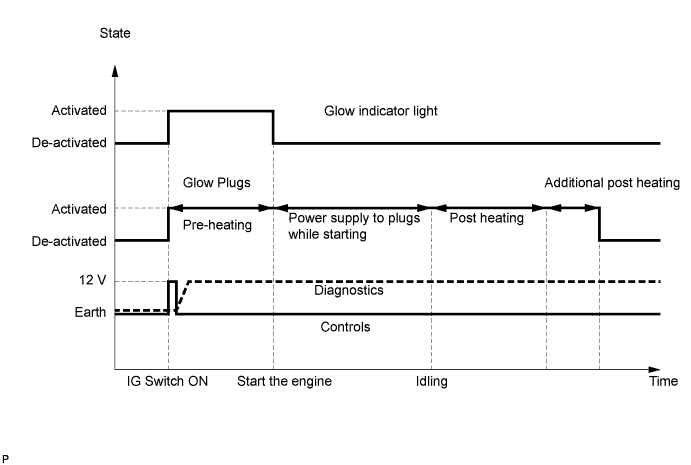
| DTC No. | DTC Detection Condition | Trouble Area | Possible to Detect | |
|---|---|---|---|---|
| Ignition Switch | Engine Run | |||
| P1349 | Short in glow plug circuit to battery power source for 2 sec. or more. |
|
ON | ON |
| P1350 | Open or short in glow plug circuit for 2 sec. or more. |
|
ON | ON |
| P1351 | Glow plug relay not commanded and glow on for 5 sec. or more. |
|
ON | ON |
| P1352 | Glow plug relay commanded and glow off for 5 sec. or more. |
|
ON | ON |
FAIL-SAFE
| DTC No. | Fail-safe Operation | Fail-safe Deactivation Condition |
|---|---|---|
| P1349 | - | - |
| P1350 | - | - |
| P1351 | - | - |
| P1352 | - | - |
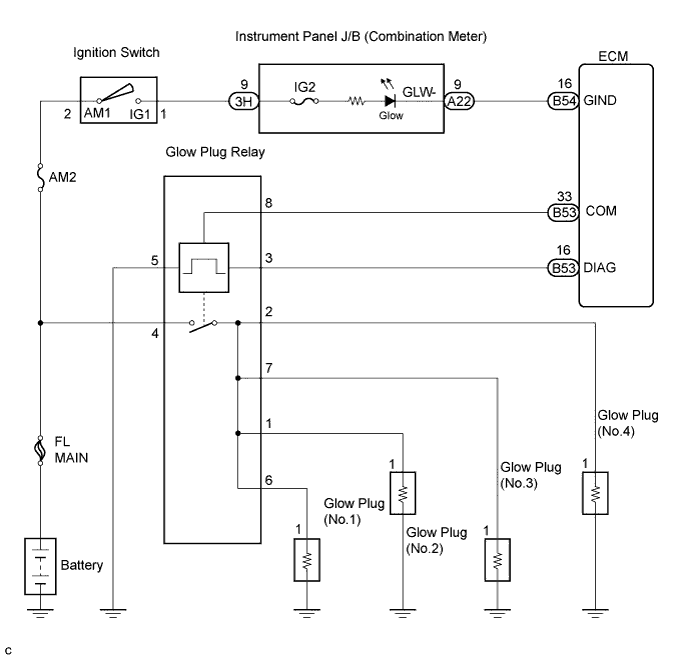
WIRING DIAGRAM
INSPECTION PROCEDURE
Tech Tips
-
When DTC P1349, P1350, P1351 or P1352 is detected, check the order of the glow plug relay by selecting the following menu items on the intelligent tester: Powertrain / Engine and ECT / Data List / Glw Plg Rly.
Result: Display (DTC output) Condition Active Before ECM setting time with the cold engine. Inactive After ECM setting time with cold engine. *1: This setting time depends on the engine coolant temperature.
-
If the ECM is replaced, variant coding (variant coding indicates the presence of vehicle accessory items, A/C, etc.) should always be performed Click here.
-
Before removing the ECM and the peripheral parts, wait at least 3 minute after turning the ignition switch off (If the cooling fan is operating, remove the ECM and the peripheral parts after the fan stops.).
PROCEDURE
-
INSPECT GLOW PLUG RELAY (VOLTAGE)
-
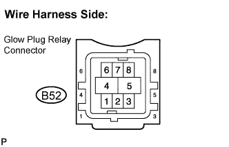
Disconnect the B52 glow plug relay connector.
-
Turn the ignition switch ON.
-
Measure the voltage according to the value(s) in the table below.
Standard voltage Tester Connection Specified Condition 4 - 5 11 to 14 V
NG 
CHECK AND REPLACE HARNESS AND CONNECTOR (BATTERY - GLOW PLUG RELAY, GLOW PLUG RELAY - BODY GROUND)
OK 
-
-
PERFORM ACTIVE TEST BY INTELLIGENT TESTER (GLOW PLUG)
-
Disconnect the N6, N7, N8 and N9 glow plug connectors.
-
Connect the intelligent tester to the DLC3.
-
Turn the ignition switch ON and turn the intelligent tester on.
-
Clear the DTC Click here.
-
Select the following menu items: Powertrain / Engine and ECT / Active Test / Glow Plug Heater Relay.
-
Perform the active test according to the value(s) in the table below.
Standard Glow plug relay active test Tester Connection Specified Condition Active test performed Glow plug (No.1) (N6-1) - Body ground 0 to 12 V Active test not performed Glow plug (No.1) (N6-1) - Body ground 0 V Tech Tips
While performing the active test, the operating sound of the glow plug relay is heard.
NG 
INSPECT GLOW PLUG (INSTALLATION) Click here
OK 
CHECK FOR INTERMITTENT PROBLEMS
-
-
INSPECT GLOW PLUG (INSTALLATION)
-
Check that the glow plug and glow plug wire are securely installed.
OK The glow plug and glow plug wire are securely installed.
NG
TIGHTEN GLOW PLUG
OK
-
-
INSPECT GLOW PLUG
-
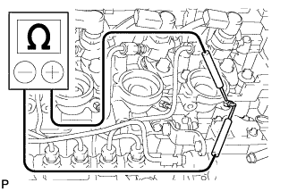
Measure the resistance according to the value(s) in the table below.
Standard resistance 10 Ω or less Tech Tips
The higher the temperature is the smaller the resistance becomes and vice versa.
NG
REPLACE GLOW PLUG
OK
-
-
CHECK HARNESS AND CONNECTOR (GLOW PLUG RELAY - ECM)
-
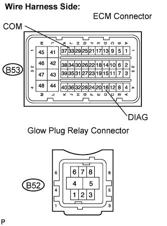
Disconnect the B53 ECM connector.
-
Disconnect the B52 glow plug relay connector.
-
Measure the resistance according to the value(s) in the table below.
Standard resistance Check for open Tester Connection Specified Condition DIAG (B53-16) - Glow plug relay (B52-3) Below 1 Ω COM (B53-33) - Glow plug relay (B52-8) Below 1 Ω Check for short Tester Connection Specified Condition DIAG (B53-16) or Glow plug relay (B52-3) - Body ground 10 kΩ or higher COM (B53-33) or Glow plug relay (B52-8) - Body ground 10 kΩ or higher
NG
REPAIR OR REPLACE HARNESS OR CONNECTOR
OK
-
-
REPLACE GLOW PLUG RELAY
NEXT
-
PERFORM ACTIVE TEST BY INTELLIGENT TESTER (GLOW PLUG)
-
Disconnect the N6, N7, N8 and N9 glow plug connectors.
-
Connect the intelligent tester to the DLC3.
-
Turn the ignition switch ON and turn the intelligent tester on.
-
Clear the DTC Click here.
-
Select the following menu items: Powertrain / Engine and ECT / Active Test / Glow Plug Heater Relay.
-
Perform the active test according to the value(s) in the table below.
Standard Glow plug relay active test Tester Connection Specified Condition Active test performed Glow plug (No.1) (N6-1) - Body ground 0 to 12 V Active test not performed Glow plug (No.1) (N6-1) - Body ground 0 V
NG
REPLACE ECM
OK
END
-