ECD SYSTEM, Diagnostic DTC:P1169

| DTC Code | DTC Name |
|---|---|
| P1169 | Converter DC / DC Piezo Voltage Too Low, Piezo Voltage Too High |
DESCRIPTION
The DC/DC converter built into the ECM boosts the battery voltage (+12V) to 70V to activate the piezo injector.
The ECM constantly monitors the boosted voltage. If the boosted voltage deviates from the normal range, the ECM determines that the DC/DC converter is malfunctioning.
| DTC No. | DTC Detection Condition | Trouble Area | Possible to Detect | |
|---|---|---|---|---|
| Ignition Switch | Engine Run | |||
| P1169 | Either the following condition (a) or (b) is met. (a) The piezo injector voltage remains less than 40 V for 2 sec. or more. (b) The piezo injector voltage remains more than 90 V for 2 sec. or more |
|
ON | ON |
-
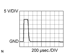
Reference:
-
The waveform between terminals #10 to #40 and PINJ1 to PINJ4 of the ECM connectors with the engine idling.
CAUTION:
-
Do not reuse the injection pipe. Be sure to replace it with a new one.
-
Do not reuse the injection nozzle seat. If the injector has been removed, be sure to replace the injector nozzle seat with a new one.
-
The injector is controlled by a voltage of +/- 70 V.
-
Be sure to connect the injector connectors correctly to prevent malfunctions in the injector.
-
Do not use any power source other than the ECM for the injector.
-
Do not apply voltage to the injector while it is not grounded to body.
-
Do not disassemble the injector.
-
Do not use the ultrasonic cleaning tool to clean the injector.
FAIL-SAFE
| DTC No. | Fail-safe Operation | Fail-safe Deactivation Condition |
|---|---|---|
| P1169 | - | - |
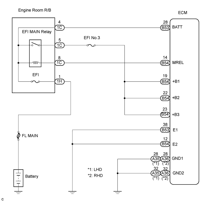
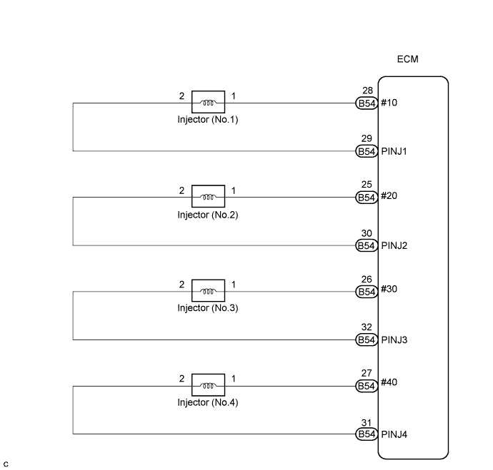
WIRING DIAGRAM
INSPECTION PROCEDURE
Tech Tips
-
When DTC P1169 is present, check the injector voltage by selecting the following menu items on the intelligent tester: Powertrain / Engine and ECT / Data List / Inj Volt.
-
If the ECM is replaced, variant coding (variant coding indicates the presence of vehicle accessory items, A/C, etc.) should always be performed Click here.
-
Before removing the ECM and the peripheral parts, wait at least 3 minute after turning the ignition switch off (If the cooling fan is operating, remove the ECM and the peripheral parts after the fan stops.).
PROCEDURE
-
CHECK IF ENGINE STARTS
Result Result Proceed To Engine starts A Engine does not start B
B 
CHECK BATTERY (VOLTAGE) Click here
A 
-
READ VALUE OF INTELLIGENT TESTER (INJECTOR VOLTAGE)
-
Connect the intelligent tester to the DLC3.
-
Start the engine and turn the intelligent tester on.
-
Select the following menu items: Powertrain / Engine and ECT / Inj Volt.
-
Read the value.
Result Display Proceed To 40 to 90 V A Other than above B
B
CHECK BATTERY (VOLTAGE) Click here
A 
CHECK FOR INTERMITTENT PROBLEMS
-
-
CHECK BATTERY (VOLTAGE)
-
Check if the battery voltage.
Note
Carry out this check with the engine stopped and ignition switch OFF.
Standard voltage 11 to 14 V
NG 
CHARGE OR REPLACE BATTERY
OK
-
-
INSPECT ECM (VOLTAGE)
-
Disconnect the B54 ECM connector.
-
Turn the ignition switch to the ON position.
-
Measure the voltage according to the value(s) in the table below.
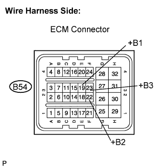
Standard voltage Tester Connection Specified Condition +B1 (B54-19) - Body ground 11 to 14 V +B2 (B54-22) - Body ground 11 to 14 V +B3 (B54-23) - Body ground 11 to 14 V
NG
CHECK AND REPAIR ECM POWER SOURCE CIRCUIT
OK
-
-
CHECK HARNESS AND CONNECTOR (ECM - BODY GROUND)
-
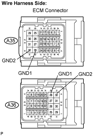
Disconnect the A35 (A36) ECM connector.
-
Measure the resistance according to the value(s) in the table below.
Standard resistance LHD Tester Connection Specified Condition GND1 (A35-28) - Body ground Below 1 Ω GND2 (A35-32) - Body ground Below 1 Ω RHD Tester Connection Specified Condition GND1 (A36-28) - Body ground Below 1 Ω GND2 (A36-32) - Body ground Below 1 Ω
NG
REPAIR OR REPLACE HARNESS OR CONNECTOR
OK
-
-
CHECK HARNESS AND CONNECTOR (ECM - BODY GROUND)
-
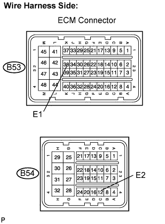
Disconnect the B53 and B54 ECM connectors.
-
Measure the resistance according to the value(s) in the table below.
Standard resistance Check for open Tester Connection Specified Condition E1 (B53-38) - Body ground Below 1 Ω E2 (B54-12) - Body ground Below 1 Ω
NG
REPAIR OR REPLACE HARNESS OR CONNECTOR
OK
-
-
CHECK CONNECTOR INSTALLATION (INJECTOR)
-
Check the injector connector installation.
OK The connectors are installed correctly.
NG
REPAIR OR REPLACE CONNECTOR
OK
-
-
CHECK INJECTOR
-
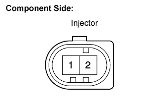
Disconnect the N1, N2, N3 and N4 injector connectors.
-
Measure the resistance according to the value(s) in the table below.
Standard resistance Tester Connection Specified Condition 1 - 2 150 to 250 kΩ
NG
REPLACE INJECTOR (S)
OK
-
-
CHECK HARNESS AND CONNECTOR (INJECTOR - ECM)
-
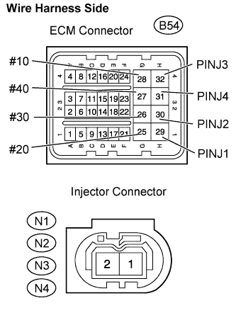
Disconnect the B54 ECM connector.
-
Disconnect the N1, N2, N3 and N4 injector connectors.
-
Measure the resistance according to the value(s) in the table below.
Standard resistance Check for open Tester Connection Specified Condition #10 (B54-28) - Injector (No.1) (N1-1) Below 1 Ω PINJ1 (B54-29) - Injector (No.1) (N1-2) Below 1 Ω #20 (B54-25) - Injector (No.2) (N2-1) Below 1 Ω PINJ2 (B54-30) - Injector (No.2) (N2-2) Below 1 Ω #30 (B54-26) - Injector (No.3) (N3-1) Below 1 Ω PINJ3 (B54-32) - Injector (No.3) (N3-2) Below 1 Ω #40 (B54-27) - Injector (No.4) (N4-1) Below 1 Ω PINJ4 (B54-31) - Injector (No.4) (N4-2) Below 1 Ω Check for short Tester Connection Specified Condition #10 (B54-28) or Injector (No.1) (N1-1) - Body ground 10 kΩ or higher PINJ1 (B54-29) or Injector (No.1) (N1-2) - Body ground 10 kΩ or higher #20 (B54-25) or Injector (No.2) (N2-1) - Body ground 10 kΩ or higher PINJ2 (B54-30) or Injector (No.2) (N2-2) - Body ground 10 kΩ or higher #30 (B54-26) or Injector (No.3) (N3-1) - Body ground 10 kΩ or higher PINJ3 (B54-32) or Injector (No.3) (N3-2) - Body ground 10 kΩ or higher #40 (B54-27) or Injector (No.4) (N4-1) - Body ground 10 kΩ or higher PINJ4 (B54-31) or Injector (No.4) (N4-2) - Body ground 10 kΩ or higher
NG
REPAIR OR REPLACE HARNESS OR CONNECTOR
OK
REPLACE ECM
-