ECD SYSTEM, Diagnostic DTC:P1114, P1192, P1668

| DTC Code | DTC Name |
|---|---|
| P1114 | Electric Injection Fuel Cut-off |
| P1192 | Hydraulic Fuel Cut-off by PCV and VCV |
| P1668 | Fuel Cut-off not Plausible |
DESCRIPTION
| DTC No. | DTC Detection Condition | Trouble Area | Possible to Detect | |
|---|---|---|---|---|
| Ignition Switch | Engine Run | |||
| P1114 | Engine cut-off function fault (Electric cut-off by injection). |
|
- | - |
| P1192 | Engine cut-off function fault (Fuel cut-off by PCV and VCV). |
|
- | - |
| P1668 | Engine cut-off function fault (Fuel cut-off plausible). (1 trip detection logic) |
|
- | - |
FAIL-SAFE
| DTC No. | Fail-safe Operation | Fail-safe Deactivation Condition |
|---|---|---|
| P1114 |
|
- |
| P1192 |
|
- |
| P1668 | Limits the engine speed (2,000 rpm). | Ignition switch OFF |
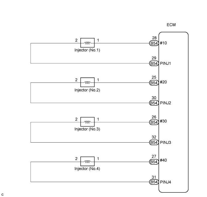
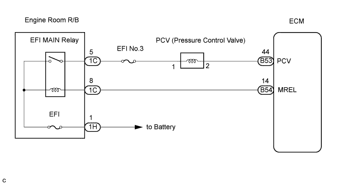
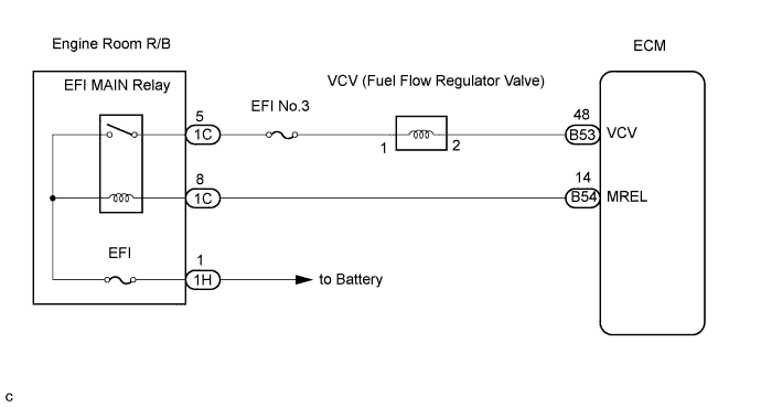
WIRING DIAGRAM
INSPECTION PROCEDURE
Tech Tips
-
If the ECM is replaced, variant coding (variant coding indicates the presence of vehicle accessory items, A/C, etc.) should always be performed Click here.
-
Before removing the ECM and the peripheral parts, wait at least 3 minute after turning the ignition switch off (If the cooling fan is operating, remove the ECM and the peripheral parts after the fan stops.).
-
When DTC P1114, P1192 or P1668 is detected, check the injector voltage by selecting the following menu items on the intelligent tester: Powertrain / Engine and ECT / Data List / Inj Volt.
-
Reference:
-
Idling: Approximately 70 V
-
This malfunction detection is done after ignition switch off.
PROCEDURE
-
CHECK DTC OUTPUT (P1114, P1192 AND/OR P1668)
-
Connect the intelligent tester to the DLC3.
-
Turn the ignition switch to the ON position and turn the intelligent tester on.
-
Select the following menu items: Powertrain / Engine and ECT / DTC.
-
Read the DTCs displayed on the intelligent tester.
Result Display (DTC Output) Proceed To P1114, P1192 and/or P1668 A Only P1192 B
B 
PERFORM ACTIVE TEST BY INTELLIGENT TESTER (OPERATE VCV) Click here
A 
-
-
CHECK INJECTOR
-
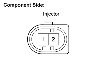
Disconnect the N1, N2, N3 and N4 injector connectors.
-
Measure the resistance according to the value(s) in the table below.
Standard resistance Tester Connection Specified Condition 1 - 2 150 to 250 kΩ
NG 
REPLACE INJECTOR (S)
OK
-
-
CHECK HARNESS AND CONNECTOR (INJECTOR - ECM)
-
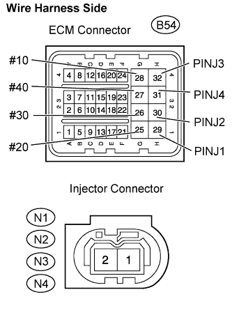
Disconnect the B54 ECM connector.
-
Disconnect the N1, N2, N3 and N4 injector connectors.
-
Measure the resistance according to the value(s) in the table below.
Standard resistance Check for open Tester Connection Specified Condition #10 (B54-28) - Injector (No.1) (N1-1) Below 1 Ω PINJ1 (B54-29) - Injector (No.1) (N1-2) Below 1 Ω #20 (B54-25) - Injector (No.2) (N2-1) Below 1 Ω PINJ2 (B54-30) - Injector (No.2) (N2-2) Below 1 Ω #30 (B54-26) - Injector (No.3) (N3-1) Below 1 Ω PINJ3 (B54-32) - Injector (No.3) (N3-2) Below 1 Ω #40 (B54-27) - Injector (No.4) (N4-1) Below 1 Ω PINJ4 (B54-31) - Injector (No.4) (N4-2) Below 1 Ω Check for short Tester Connection Specified Condition #10 (B54-28) or Injector (No.1) (N1-1) - Body ground 10 kΩ or higher PINJ1 (B54-29) or Injector (No.1) (N1-2) - Body ground 10 kΩ or higher #20 (B54-25) or Injector (No.2) (N2-1) - Body ground 10 kΩ or higher PINJ2 (B54-30) or Injector (No.2) (N2-2) - Body ground 10 kΩ or higher #30 (B54-26) or Injector (No.3) (N3-1) - Body ground 10 kΩ or higher PINJ3 (B54-32) or Injector (No.3) (N3-2) - Body ground 10 kΩ or higher #40 (B54-27) or Injector (No.4) (N4-1) - Body ground 10 kΩ or higher PINJ4 (B54-31) or Injector (No.4) (N4-2) - Body ground 10 kΩ or higher
NG
REPAIR OR REPLACE HARNESS OR CONNECTOR
OK
-
-
CHECK POWER SOURCE CIRCUIT
-
Check that the battery voltage, ECM power source voltage, and the ground condition of the ECM are normal.
OK The battery voltage, ECM power source voltage, and the ground condition of the ECM are normal. Tech Tips
Make sure that the battery is not discharged during the inspection.
NG
REPAIR POWER SOURCE CIRCUIT
OK
-
-
CHECK DTC OUTPUT (REFER TO RESULT OF STEP 1)
Tech Tips
Read the output DTCs and proceed to appropriate step shown in the table below.
Result Display (DTC Output) Proceed To Except P1668 A Include P1668 B
B
PERFORM ACTIVE TEST BY INTELLIGENT TESTER (OPERATE VCV) Click here
A 
REPLACE ECM
-
PERFORM ACTIVE TEST BY INTELLIGENT TESTER (OPERATE VCV)
-
Connect the intelligent tester to the DLC3.
-
Turn the ignition switch to the ON position and turn the intelligent tester on.
-
Clear the DTC Click here.
-
Select the following menu items: Powertrain / Engine and ECT / Active Test / Flow Regulator.
-
Check the operation of the VCV while operating it using the intelligent tester.
OK Flow regulator active test Condition Active test performed VCV vibrates Active test not performed VCV does not vibrate
NG
CHECK VCV Click here
OK
-
-
PERFORM ACTIVE TEST BY INTELLIGENT TESTER (OPERATE PCV)
-
Connect the intelligent tester to the DLC3.
-
Turn the ignition switch to the ON position and turn the intelligent tester on.
-
Clear the DTC Click here.
-
Select the following menu items: Powertrain / Engine and ECT / Active Test / Pres Regul.
-
Check the operation of the PCV while operating it using the intelligent tester.
OK Fuel regulator pressure active test Condition Active test performed PCV vibrates Active test not performed PCV does not vibrate
NG
CHECK PCV Click here
OK
-
-
CHECK IF DTC RECURS (P1114, P1192 AND/OR P1668)
-
Connect the intelligent tester to the DLC3.
-
Clear the DTC Click here.
-
Start the engine.
-
Turn the intelligent tester on.
-
Stop the engine and wait for 3 minutes.
-
Select the following menu items: Powertrain / Engine and ECT / DTC.
-
Read the DTCs displayed on the intelligent tester.
Result Display (DTC Output) Proceed To No output A P1114, P1192 and/or P1668 B
B
REPLACE ECM
A
END
-
-
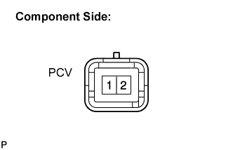
CHECK PCV
-
Disconnect the B43 PCV connector.
-
Measure the resistance according to the value(s) in the table below.
Standard resistance Tester Connection Specified Condition 1 - 2 1.5 to 15 Ω
NG
REPLACE SUPPLY PUMP (PCV)
OK
-
-
CHECK HARNESS AND CONNECTOR (PCV - ECM)
-
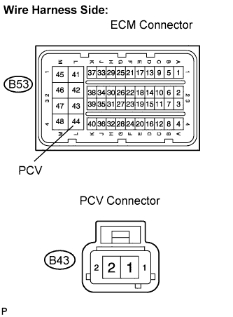
Disconnect the B53 ECM connector.
-
Disconnect the B43 PCV connector.
-
Measure the resistance according to the value(s) in the table below.
Standard resistance Check for open Tester Connection Specified Condition PCV (B53-44) - PCV (B43-2) Below 1 Ω Check for short Tester Connection Specified Condition PCV (B53-44) or PCV (B43-2) - Body ground 10 kΩ or higher
NG
REPAIR OR REPLACE HARNESS OR CONNECTOR
OK
-
-
REPLACE SUPPLY PUMP (PCV)
NEXT
-
CHECK IF DTC RECURS (P1114, P1192 AND/OR P1668)
-
Connect the intelligent tester to the DLC3.
-
Clear the DTC Click here.
-
Start the engine.
-
Turn the intelligent tester on.
-
Stop the engine and wait for 3 minutes.
-
Select the following menu items: Powertrain / Engine and ECT / DTC.
-
Read the DTCs displayed on the intelligent tester.
Result Display (DTC Output) Proceed To No output A P1114, P1192 and/or P1668 B
B
REPLACE ECM
A
END
-
-
CHECK VCV
-
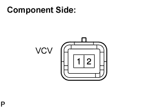
Disconnect the B33 VCV connector.
-
Measure the resistance according to the value(s) in the table below.
Standard resistance Tester Connection Specified Condition 1 - 2 1.5 to 15 Ω
NG
REPLACE SUPPLY PUMP (VCV)
OK
-
-
CHECK HARNESS AND CONNECTOR (VCV - ECM)
-
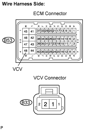
Disconnect the B53 ECM connector.
-
Disconnect the B33 VCV connector.
-
Measure the resistance according to the value(s) in the table below.
Standard resistance Check for open Tester Connection Specified Condition VCV (B53-48) - VCV (B33-2) Below 1 Ω Check for short Tester Connection Specified Condition VCV (B53-48) or VCV (B33-2) - Body ground 10 kΩ or higher
NG
REPAIR OR REPLACE HARNESS OR CONNECTOR
OK
-
-
REPLACE SUPPLY PUMP (VCV)
NEXT
-
CHECK IF DTC RECURS (P1114, P1192 AND/OR P1668)
-
Connect the intelligent tester to the DLC3.
-
Clear the DTC Click here.
-
Start the engine.
-
Turn the intelligent tester on.
-
Stop the engine and wait for 3 minutes.
-
Select the following menu items: Powertrain / Engine and ECT / DTC.
-
Read the DTCs displayed on the intelligent tester.
Result Display (DTC Output) Proceed To No output A P1114, P1192 and/or P1668 B
B
REPLACE ECM
A
END
-