ECD SYSTEM, Diagnostic DTC:P1113, P1166, P1167, P1198

| DTC Code | DTC Name |
|---|---|
| P1113 | Common Rail Pressure Controller PI Controller Drift, Common Rail Pressure Too Low |
| P1166 | Common Rail Pressure Controller PI Controller Drift, Common Rail Pressure Too High |
| P1167 | Common Rail Pressure Controller Pressure Oscillation, Dynamic Test |
| P1198 | Common Rail Pressure Controller VCV Adaptation, Insufficient Fuel Flow |
DESCRIPTION
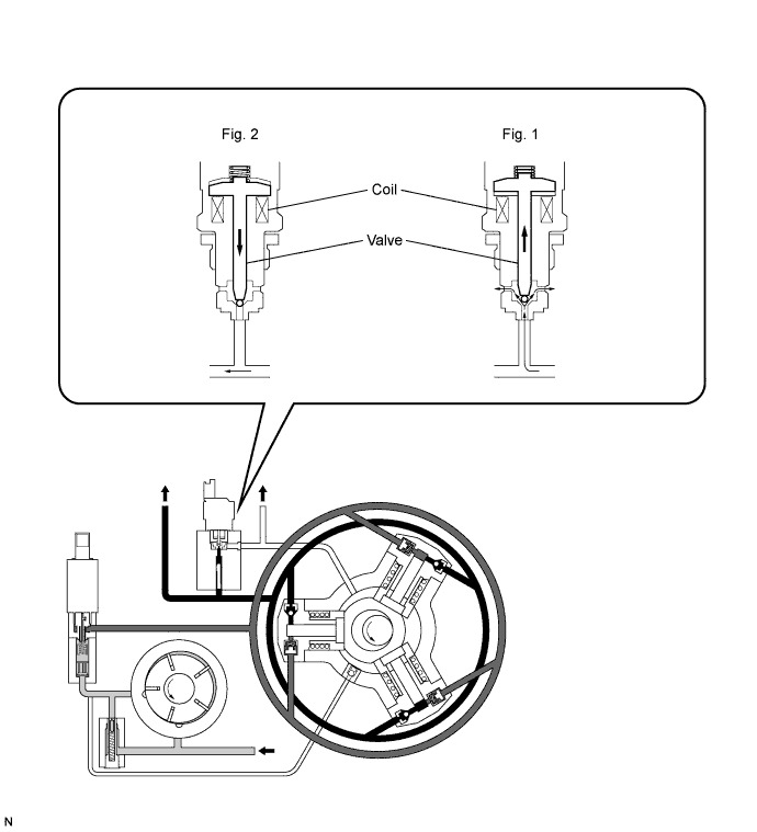
This circuit adjusts the PCV (pressure control valve) opening angle based on the signals from the ECM in order to control the pressure in the common rail. When the ignition switch is turned to the ON position, the coil attracts the valve based on the signals from the ECM to close the fuel path.
If the ECM detects that the fuel pressure in the common rail is likely to exceed the specified value based on the signals from the pressure sensor on the common rail, this circuit controls the current to the coil to open the valve. As a result, the fuel pressure is reduced to maintain the specified pressure.
If the ignition switch is turned off, the current to the control valve coil is shut off and fuel pressure opens the valve. If the fuel pressure drops below the spring force of the control valve, the valve closes.
The PCV is normaly closed by return spring. This means that when no signal is applied to the coil, the pressure in the common rail will be not 0. In this way the valve provide a minimum pressure of 5 MPa (50 bars, 725 psi).
When a current is applied to the coil, an additional force is added to that of the spring. The control signal is DUTY, and the average current is 0.6 A with peak of 2 A. The injector needle returns spring tension is set to 7 MPa (70 bars, 1,015 psi). This pressure is higher than the pressure of PCV, which is set at 5 MPa (50 bars, 725 psi). In this way, the injector will not open if PCV does not operate.
Tech Tips
When the battery becomes dead or the battery terminal cables are disconnected with the ignition switch in the ON position, DTC P1113 and P1198 are output.
| DTC No. | DTC Detection Condition | Trouble Area | Possible to Detect | |
|---|---|---|---|---|
| Ignition Switch | Engine Run | |||
| P1113 | The pressure in the common rail is less than the thresholds. (1 trip detection logic) |
|
- | - |
| P1166 | The pressure in the common rail exceeds the thresholds. (1 trip detection logic) |
|
- | - |
| P1167 | Pressure controller oscillation or dynamic test (3 trip detection logic) |
|
- | - |
| P1198 | VCV adaptation insufficient fuel flow (1 trip detection logic) |
|
- | - |
-
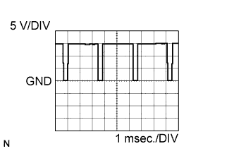
Reference:
-
The waveform between terminals PCV and E2 of the ECM connectors.
FAIL-SAFE
| DTC No. | Fail-safe Operation | Fail-safe Deactivation Condition |
|---|---|---|
| P1113 | - | - |
| P1166 |
|
Normal condition is restored. |
| P1167 | - | - |
| P1198 | Engine reaction: engine stall | Next engine start. |
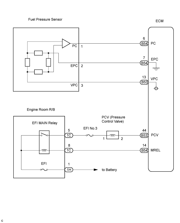
WIRING DIAGRAM
INSPECTION PROCEDURE
Tech Tips
-
When DTC P1113, P1166, P1167 or P1198 is detected, check the target common rail pressure by selecting the following menu items on the intelligent tester: Powertrain / Engine and ECT / Data List / Tag Comn Rail Pres.
-
When DTC P1113, P1166, P1167 or P1198 is detected, check the common rail pressure by selecting the following menu items on the intelligent tester: Powertrain / Engine and ECT / Data List / Comn Rail Pres.
-
Reference:
-
Idling: 220 bars
-
2,500 rpm: 420 bars
-
IG switch OFF: 0 to 20 bars
-
When DTC P1113, P1166, P1167 or P1198 is detected, check the pressure regulator duty by selecting the following menu items on the intelligent tester: Powertrain / Engine and ECT / Data List / Pres Regul Duty.
Reference: Condition Display (Pressure regulator duty) Idling 12 to 18% Minimum pressure 0% Maximum pressure 30% -
If DTC P0001, P0002, P0003, P0004, P2141, P2142, or P2143 is output at the same time as DTC P0089, P0091, P0092, or P1210, a malfunction may be present in the EFI main relay circuit Click here.
-
If the ECM is replaced, variant coding (variant coding indicates the presence of vehicle accessory items, A/C, etc.) should always be performed Click here.
-
Before removing the ECM and the peripheral parts, wait at least 3 minute after turning the ignition switch off (If the cooling fan is operating, remove the ECM and the peripheral parts after the fan stops.).
PROCEDURE
-
CHECK DTC OUTPUT (OTHER THAN P1113, P1166, P1167 AND/OR P1198)
-
Connect the intelligent tester to the DLC3.
-
Turn the ignition switch to the ON position and turn the intelligent tester on.
-
Select the following menu items: Powertrain / Engine and ECT / DTC.
-
Read the DTCs.
Result Display (DTC output) Proceed To P1113, P1166, P1167 and/or P1198 A P1113, P1166, P1167 and/or P1198 and other DTCs B Tech Tips
If any other codes besides P1113, P1166, P1167 and P1167 are output, perform the troubleshooting for those DTCs first.
B 
GO TO DTC CHART
A 
-
-
CHECK FUEL LEAK (INSPECT HIGH-PRESSURE FUEL PARTS FOR FUEL LEAKS)
-
Visually check the supply pump, injector and fuel line located between the supply pump and the common rail for fuel leaks or fuel pressure leaks. Also, perform the same on the fuel line between the common rail and the injector.
Tech Tips
Fuel leaks inside the components (Supply pump, etc.) may result.
NG
REPAIR OR REPLACE FUEL LEAK
OK
-
-
PERFORM ACTIVE TEST USING INTELLIGENT TESTER (OPERATE VCV)
-
Connect the intelligent tester to the DLC3.
-
Turn the ignition switch to the ON position and turn the intelligent tester on.
-
Clear the DTC Click here.
-
Select the following menu items: Powertrain / Engine and ECT / Active Test / Flow Regulator.
-
Check the operation of the VCV while operating it using the intelligent tester.
Standard Flow regulator active test Condition Active test performed VCV vibrates Active test not performed VCV does not vibrate
NG 
CHECK VCV Click here
OK
-
-
PERFORM ACTIVE TEST USING INTELLIGENT TESTER (OPERATE PCV)
-
Connect the intelligent tester to the DLC3.
-
Turn the ignition switch to the ON position and turn the intelligent tester on.
-
Clear the DTC Click here.
-
Select the following menu items: Powertrain / Engine and ECT / Active Test / Pres Regul.
-
Check the operation of the PCV while operating it using the intelligent tester.
Standard Fuel regulator pressure active test Condition Active test performed PCV vibrates Active test not performed PCV does not vibrate
NG
CHECK PCV Click here
OK
-
-
CHECK HARNESS AND CONNECTOR (FUEL PRESSURE SENSOR - ECM)
-
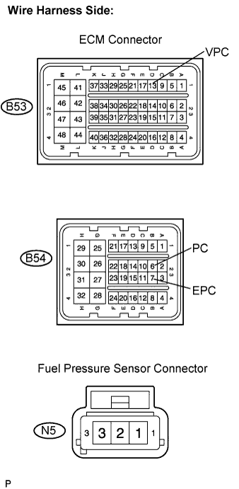
Disconnect the B53 and B54 ECM connectors.
-
Disconnect the N5 fuel pressure sensor connector.
-
Measure the resistance according to the value(s) in the table below.
Standard resistance Check for open Tester Connection Specified Condition VPC (B53-13) - VPC (N5-3) Below 1 Ω PC (B54-6) - PC (N5-1) Below 1 Ω EPC (B54-7) - EPC (N5-2) Below 1 Ω Check for short Tester Connection Specified Condition VPC (B53-13) or VPC (N5-3) - Body ground 10 kΩ or higher PC (B54-6) or PC (N5-1) - Body ground 10 kΩ or higher EPC (B54-7) or EPC (N5-2) - Body ground 10 kΩ or higher
NG
REPAIR OR REPLACE HARNESS OR CONNECTOR
OK
-
-
REPLACE FUEL PRESSURE SENSOR
NEXT
-
CHECK IF DTC RECURS (P1113, P1166, P1167 AND/OR P1198)
-
Connect the intelligent tester to the DLC3.
-
Clear the DTC Click here.
-
Start the engine.
-
Select the following menu items: Powertrain / Engine and ECT / DTC.
-
Read the DTCs displayed on the intelligent tester.
Result Display (DTC output) Proceed To No output A P1113, P1166, P1167 and/or P1198 B
B
REPLACE ECM
A 
END
-
-
CHECK PCV
-
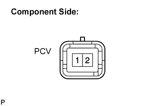
Disconnect the B43 PCV connector.
-
Measure the resistance according to the value(s) in the table below.
Standard resistance Tester Connection Specified Condition 1 - 2 1.5 to 15 Ω
NG
REPLACE SUPPLY PUMP (PCV)
OK
-
-
INSPECT PCV (VOLTAGE)
-
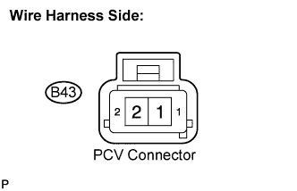
Disconnect the B43 PCV connector.
-
Turn the ignition switch to the ON position.
-
Measure the voltage according to the value(s) in the table below.
Standard voltage Tester Connection Specified Condition PCV (B43-1) - Body ground 11 to 14 V
NG
CHECK HARNESS AND CONNECTOR (EFI MAIN RELAY - PCV) Click here
OK
-
-
CHECK HARNESS AND CONNECTOR (PCV - ECM)
-
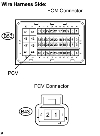
Disconnect the B53 ECM connector.
-
Disconnect the B43 PCV connector.
-
Measure the resistance according to the value(s) in the table below.
Standard resistance Check for open Tester Connection Specified Condition PCV (B53-44) - PCV (B43-2) Below 1 Ω Check for short Tester Connection Specified Condition PCV (B53-44) or PCV (B43-2) - Body ground 10 kΩ or higher
NG
REPAIR OR REPLACE HARNESS OR CONNECTOR
OK
-
-
REPLACE SUPPLY PUMP (PCV)
NEXT
-
CHECK IF DTC RECURS (P1113, P1166, P1167 AND/OR P1198)
-
Connect the intelligent tester to the DLC3.
-
Clear the DTC Click here.
-
Start the engine and drive the vehicle for 20 minutes.
-
Turn the intelligent tester on.
-
Select the following menu items: Powertrain / Engine and ECT / DTC.
-
Read the DTCs displayed on the intelligent tester.
Result Display (DTC output) Proceed To No output A P1113, P1166, P1167 and/or P1198 B
B
REPLACE ECM
A
END
-
-
CHECK HARNESS AND CONNECTOR (EFI MAIN RELAY - PCV)
-
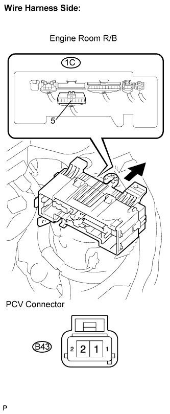
Disconnect the B43 PCV connector.
-
Remove the engine room R/B.
-
Remove the engine room R/B lower cover.
-
Disconnect the 1C engine room R/B connector.
-
Measure the resistance according to the value(s) in the table below.
Standard resistance Check for open Tester Connection Specified Condition PCV (B43-1) - Engine room R/B (1C-5) Below 1 Ω Check for short Tester Connection Specified Condition PCV (B43-1) or Engine room R/B (1C-5) - Body ground 10 kΩ or higher
NG
REPAIR OR REPLACE HARNESS OR CONNECTOR
OK
-
-
INSPECT EFI MAIN RELAY (VOLTAGE)
-
Remove the engine room R/B.
-
Remove the engine room R/B lower cover.
-
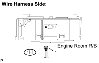
Disconnect the 1H engine room R/B connector.
-
Measure the voltage according to the value(s) in the table below.
Standard voltage Tester Connection Specified Condition Engine room R/B (1H-1) - Body ground 11 to 14 V
NG
CHECK AND REPAIR HARNESS AND CONNECTOR (BATTERY - EFI MAIN RELAY)
OK
-
-
CHECK HARNESS AND CONNECTOR (EFI MAIN RELAY - ECM)
-
Disconnect the B54 ECM connector.
-
Remove the engine room R/B.
-
Remove the engine room R/B lower cover.
-
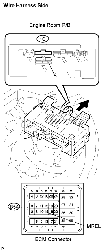
Disconnect the 1C engine room R/B connector.
-
Measure the resistance according to the value(s) in the table below.
Standard resistance Check for open Tester Connection Specified Condition MREL (B54-14) - Engine room R/B (1C-8) Below 1 Ω Check for short Specified Condition Specified Condition MREL (B54-14) or Engine room R/B (1C-8) - Body ground 10 kΩ or higher
NG
REPAIR OR REPLACE HARNESS OR CONNECTOR
OK
-
-
REPLACE ENGINE ROOM R/B (EFI MAIN RELAY)
NEXT
-
CHECK IF DTC RECURS (P1113, P1166, P1167 AND/OR P1198)
-
Connect the intelligent tester to the DLC3.
-
Clear the DTC Click here.
-
Start the engine and drive the vehicle for 20 minutes.
-
Turn the intelligent tester on.
-
Select the following menu items: Powertrain / Engine and ECT / DTC.
-
Read the DTCs displayed on the intelligent tester.
Result Display (DTC output) Proceed To No output A P1113, P1166, P1167 and/or P1198 B
B
REPLACE ECM
A
END
-
-
CHECK VCV
-
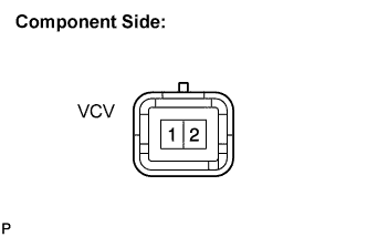
Disconnect the B33 VCV connector.
-
Measure the resistance according to the value(s) in the table below.
Standard resistance Tester Connection Specified Condition 1 - 2 1.5 to 15 Ω
NG
REPLACE SUPPLY PUMP (VCV)
OK
-
-
CHECK HARNESS AND CONNECTOR (VCV - ECM)
-
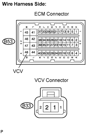
Disconnect the B53 ECM connector.
-
Disconnect the B33 VCV connector.
-
Measure the resistance according to the value(s) in the table below.
Standard resistance Check for open Tester Connection Specified Condition VCV (B53-48) - VCV (B33-2) Below 1 Ω Check for short Tester Connection Specified Condition VCV (B53-48) or VCV (B33-2) - Body ground 10 kΩ or higher
NG
REPAIR OR REPLACE HARNESS OR CONNECTOR
OK
-
-
REPLACE SUPPLY PUMP (VCV)
NEXT
-
CHECK IF DTC RECURS (P1113, P1166, P1167 AND/OR P1198)
-
Connect the intelligent tester to the DLC3.
-
Clear the DTC Click here.
-
Start the engine and drive the vehicle for 20 minutes.
-
Turn the intelligent tester on.
-
Select the following menu items: Powertrain / Engine and ECT / DTC.
-
Read the DTCs displayed on the intelligent tester.
Result Display (DTC output) Proceed To No output A P1113, P1166, P1167 and/or P1198 B
B
REPLACE ECM
A
END
-