ECD SYSTEM, Diagnostic DTC:P0658, P0659

| DTC Code | DTC Name |
|---|---|
| P0658 | 5V Supply No.1 Voltage Supply Too Low |
| P0659 | 5V Supply No.1 Voltage Supply Too High |
DESCRIPTION
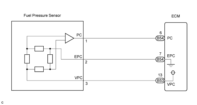
The ECM supplies power voltage (5 V) to the fuel pressure sensor. Using this voltage, the fuel pressure sensor converts the fuel pressure in the common rail to an electrical signal, and sends it to the ECM.
| DTC No. | DTC Detection Condition | Trouble Area | Possible to Detect | |
|---|---|---|---|---|
| Ignition Switch | Engine Run | |||
| P0658 | The power supply voltage from the ECM to the fuel pressure sensor is less than 4.7 V for 0.1 sec. or more. (1 trip detection logic) |
|
ON | ON |
| P0659 | The power supply voltage from the ECM to the fuel pressure sensor is more than 5.3 V for 0.1 sec. or more. (1 trip detection logic) |
|
ON | ON |
FAIL-SAFE
| DTC No. | Fail-safe Operation | Fail-safe Deactivation Condition |
|---|---|---|
| P0658 |
|
Normal condition is restored. |
| P0659 |
|
Normal condition is restored. |
WIRING DIAGRAM
INSPECTION PROCEDURE
Tech Tips
-
When DTC P0658 or P0659 is detected, check the sensor supply voltage by selecting the following menu items on the intelligent tester: Powertrain / Engine and ECT / Data List / Sensor Supply Voltage.
-
If the ECM is replaced, variant coding (variant coding indicates the presence of vehicle accessory items, A/C, etc.) should always be performed Click here.
-
Before removing the ECM and the peripheral parts, wait at least 3 minute after turning the ignition switch off (If the cooling fan is operating, remove the ECM and the peripheral parts after the fan stops.).
PROCEDURE
-
READ VALUE USING INTELLIGENT TESTER (SENSOR SUPPLY VOLTAGE)
-
Connect the intelligent tester to the DLC3.
-
Turn the ignition switch to the ON position and turn the intelligent tester on.
-
Select the following menu items: Powertrain / Engine and ECT / Data List / Sensor Supply Voltage1.
-
Read the value.
Result 4.75 to 5.25 V
NG 
INSPECT ECM (VOLTAGE) Click here
OK 
CHECK FOR INTERMITTENT PROBLEMS
-
-
INSPECT ECM (VOLTAGE)
-
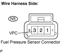
Disconnect the N5 fuel pressure sensor connector.
-
Turn the ignition switch to the ON position.
-
Measure the voltage according to the value(s) in the table below.
Standard voltage Tester Connection Specified Condition VPC (N5-3) - Body ground 4.7 to 5.3 V
NG
CHECK HARNESS AND CONNECTOR (FUEL PRESSURE SENSOR - ECM) Click here
OK
REPLACE FUEL PRESSURE SENSOR
-
-
CHECK HARNESS AND CONNECTOR (FUEL PRESSURE SENSOR - ECM)
-
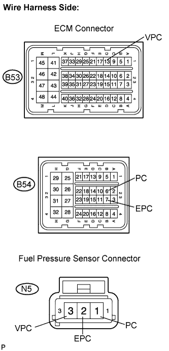
Disconnect the B53 and B54 ECM connectors.
-
Disconnect the N5 fuel pressure sensor connector.
-
Measure the resistance according to the value(s) in the table below.
Standard resistance Check for open Tester Connection Specified Condition VPC (B53-13) - VPC (N5-3) Below 1 Ω PC (B54-6) - PC (N5-1) Below 1 Ω EPC (B54-7) - EPC(N5-2) Below 1 Ω Check for short Tester Connection Specified Condition VPC (B53-13) or VPC (N5-3) - Body ground 10 kΩ or higher PC (B54-6) or PC (N5-1) - Body ground 10 kΩ or higher EPC (B54-7) or EPC (N5-2) - Body ground 10 kΩ or higher
NG 
REPAIR OR REPLACE HARNESS OR CONNECTOR
OK 
-
-
CHECK POWER SOURCE CIRCUIT
-
Check that the battery voltage, ECM power source voltage, and the ground condition of the ECM are normal.
OK The battery voltage, ECM power source voltage, and the ground condition of the ECM are normal. Tech Tips
Make sure that the battery is not discharged during the inspection.
NG
REPAIR POWER SOURCE CIRCUIT
OK
REPLACE ECM
-