ECD SYSTEM, Diagnostic DTC:P0606, P1197, P1641

| DTC Code | DTC Name |
|---|---|
| P0606 | ECM Processor |
| P1197 | Piezo Power Stage Voltage Control / Global Incapacity |
| P1641 | Piezo Power Stage Initializing of Driver Failed |
DESCRIPTION
| DTC No. | DTC Detection Condition | Trouble Area | Possible to Detect | |
|---|---|---|---|---|
| Ignition Switch | Engine Run | |||
| P0606 | Injector circuit fault |
|
ON | ON |
| P1197 | Injector circuit fault (1 trip detection logic) |
|
ON | ON |
| P1641 | Injector circuit fault |
|
ON | ON |
-
Reference:
-
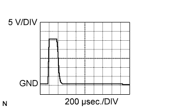
The waveform between terminals #10 to #40 and PINJ1 to PINJ4 of the ECM connectors with the engine idling.
CAUTION:
-
Do not reuse the injection pipe. Be sure to replace it with a new one.
-
Do not reuse the injection nozzle seat. If the injector has been removed, be sure to replace the injector nozzle seat with a new one.
-
The injector is controlled by a voltage of +/- 70 V.
-
Be sure to connect the injector connectors correctly to prevent malfunctions in the injector.
-
Do not use any power source other than the ECM for the injector.
-
Do not apply voltage to the injector while it is not grounded to body.
-
Do not disassemble the injector.
-
Do not use the ultrasonic cleaning tool to clean the injector.
FAIL-SAFE
| DTC No. | Fail-safe Operation | Fail-safe Deactivation Condition |
|---|---|---|
| P0606 | DC/DC converter control inhibited. | - |
| P1197 |
|
- |
| P1641 |
|
- |
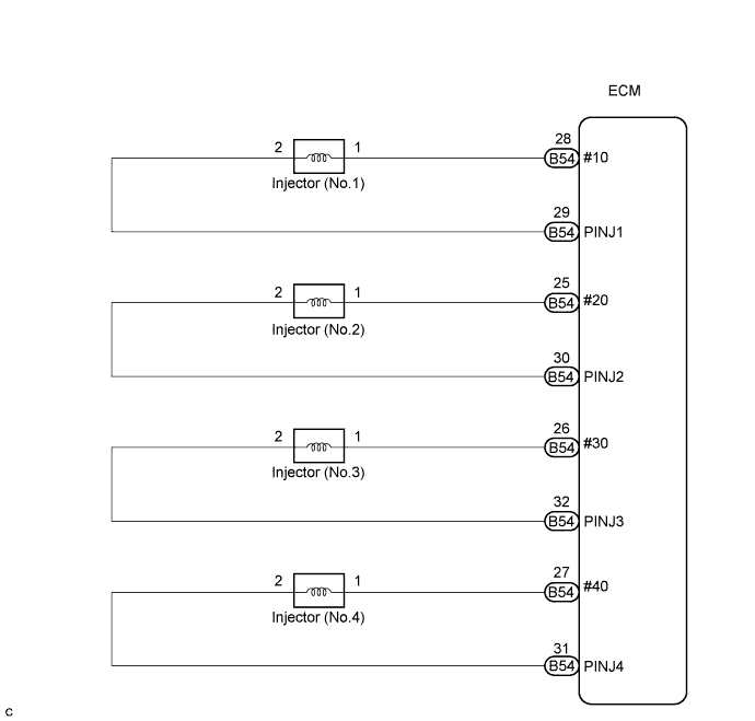
WIRING DIAGRAM
INSPECTION PROCEDURE
Tech Tips
-
If the ECM is replaced, variant coding (variant coding indicates the presence of vehicle accessory items, A/C, etc.) should always be performed Click here.
-
Before removing the ECM and the peripheral parts, wait at least 3 minute after turning the ignition switch off (If the cooling fan is operating, remove the ECM and the peripheral parts after the fan stops.).
PROCEDURE
-
CHECK INJECTOR
-
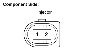
Disconnect the N1, N2, N3 and N4 injector connectors.
-
Measure the resistance according to the value(s) in the table below.
Standard resistance Tester Connection Specified Condition 1 - 2 150 to 250 kΩ
NG 
REPLACE INJECTOR(S)
OK 
-
-
CHECK CONNECTORS (INSTALLATION)
-
Check the installation condition the ECM and injector connector.
OK The connectors all installed correctly.
NG
REPAIR OR REPLACE CONNECTOR
OK
-
-
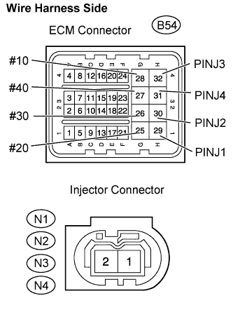
CHECK HARNESS AND CONNECTOR (INJECTOR - ECM)
-
Disconnect the B54 ECM connector.
-
Disconnect the N1, N2, N3 and N4 injector connectors.
-
Measure the resistance according to the value(s) in the table below.
Standard resistance Check for open Tester Connection Specified Condition #10 (B54-28) - Injector (No.1) (N1-1) Below 1 Ω PINJ1 (B54-29) - Injector (No.1) (N1-2) Below 1 Ω #20 (B54-25) - Injector (No.2) (N2-1) Below 1 Ω PINJ2 (B54-30) - Injector (No.2) (N2-2) Below 1 Ω #30 (B54-26) - Injector (No.3) (N3-1) Below 1 Ω PINJ3 (B54-32) - Injector (No.3) (N3-2) Below 1 Ω #40 (B54-27) - Injector (No.4) (N4-1) Below 1 Ω PINJ4 (B54-31) - Injector (No.4) (N4-2) Below 1 Ω Check for short Tester Connection Specified Condition #10 (B54-28) or Injector (No.1) (N1-1) - Body ground 10 kΩ or higher PINJ1 (B54-29) or Injector (No.1) (N1-2) - Body ground 10 kΩ or higher #20 (B54-25) or Injector (No.2) (N2-1) - Body ground 10 kΩ or higher PINJ2 (B54-30) or Injector (No.2) (N2-2) - Body ground 10 kΩ or higher #30 (B54-26) or Injector (No.3) (N3-1) - Body ground 10 kΩ or higher PINJ3 (B54-32) or Injector (No.3) (N3-2) - Body ground 10 kΩ or higher #40 (B54-27) or Injector (No.4) (N4-1) - Body ground 10 kΩ or higher PINJ4 (B54-31) or Injector (No.4) (N4-2) - Body ground 10 kΩ or higher
NG
REPAIR OR REPLACE HARNESS OR CONNECTOR
OK
-
-
CHECK POWER SOURCE CIRCUIT
-
Check that the battery voltage, ECM power source voltage, and the ground condition of the ECM are normal.
OK The battery voltage, ECM power source voltage, and the ground condition of the ECM are normal. Tech Tips
Make sure that the battery is not discharged during the inspection.
NG
REPAIR POWER SOURCE CIRCUIT
OK
-
-
CHECK IF DTC RECURS (P0606, P1197 AND/OR P1641)
-
Connect the intelligent tester to the DLC3.
-
Clear the DTC Click here.
-
Turn the ignition switch to the ON position and turn the intelligent tester on.
-
Select the following menu items: Powertrain / Engine and ECT / DTC.
-
Read the DTCs displayed on the intelligent tester.
Result Display (DTC Output) Proceed To No output A P0606, P1197 and/or P1641 B
B
REPLACE ECM
A 
END
-