ECD SYSTEM, Diagnostic DTC:P0571

| DTC Code | DTC Name |
|---|---|
| P0571 | Stop Light Switch Main Sensor not Plausible |
DESCRIPTION
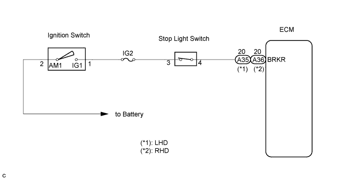
The stop light switch signal is used to detect when the brakes have been applied. The stop light signal voltage is the same as the voltage supplied to the stop light.
| DTC No. | DTC Detection Condition | Trouble Area | Possible to Detect | |
|---|---|---|---|---|
| Ignition Switch | Engine Run | |||
| P0571 | Malfunction in the stop light switch |
|
- | - |
FAIL-SAFE
| DTC No. | Fail-safe Operation | Fail-safe Deactivation Condition |
|---|---|---|
| P0571 | - | - |
WIRING DIAGRAM
INSPECTION PROCEDURE
Tech Tips
-
When DTC P0571 is detected, check the stop light switch by selecting the following menu items on the intelligent tester: Powertrain / Engine and ECT / Data List / Stop Light SW.
-
If the ECM is replaced, variant coding (variant coding indicates the presence of vehicle accessory items, A/C, etc.) should always be performed Click here.
-
Before removing the ECM and the peripheral parts, wait at least 3 minute after turning the ignition switch off (If the cooling fan is operating, remove the ECM and the peripheral parts after the fan stops.).
PROCEDURE
-
READ VALUE OF INTELLIGENT TESTER (STOP LIGHT SWITCH)
-
Connect the intelligent tester to the DLC3.
-
Turn the ignition switch to the ON position and turn the intelligent tester on.
-
Select the following menu items: Powertrain / Engine and ECT / Data List / Stop Light SW.
-
Read the value.
OK Brake Pedal Specified Condition Depressed STP Signal ON Released STP Signal OFF
NG 
CHECK STOP LIGHT SWITCH Click here
OK 
CHECK FOR INTERMITTENT PROBLEMS
-
-
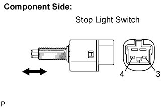
CHECK STOP LIGHT SWITCH
-
Disconnect the A17 stop light switch connector.
-
Measure the resistance according to the value(s) in the table below.
Standard resistance Tester Connection Brake Pedal Specified Condition 3 - 4 Depressed 10 kΩ or higher 3 - 4 Released Below 1 Ω
NG 
REPLACE STOP LIGHT SWITCH
OK 
-
-
INSPECT STOP LIGHT SWITCH (VOLTAGE)
-
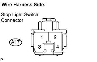
Disconnect the A17 stop light switch connector.
-
Turn the ignition switch to the ON position.
-
Measure the voltage according to the value(s) in the table below.
Standard voltage Tester Connection Specified Condition Stop light switch (A17-3) - Body ground 11 to 14 V
NG
CHECK AND REPLACE HARNESS AND CONNECTOR (STOP LIGHT SWITCH - BATTERY)
OK
-
-
CHECK HARNESS AND CONNECTOR (STOP LIGHT SWITCH - ECM)
-
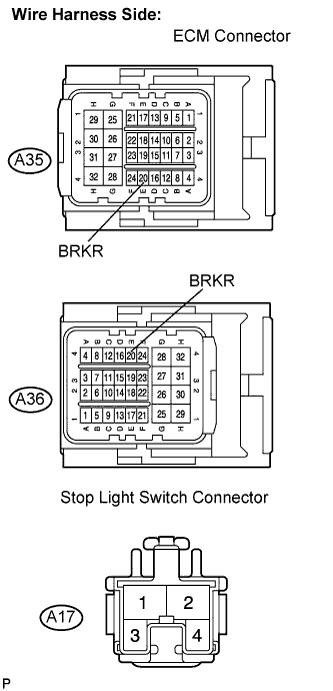
Disconnect the A35 (A36) ECM connector.
-
Disconnect the A17 stop light switch connector.
-
Measure the resistance according to the value(s) in the table below.
Standard resistance (Check for open) LHD Tester Connection Specified Condition BRKR (A35-20) - Stop light switch (A17-4) Below 1 Ω RHD Tester Connection Specified Condition BRKR (A36-20) - Stop light switch (A17-4) Below 1 Ω Standard resistance (Check for short) LHD Tester Connection Specified Condition BRKR (A35-20) or Stop light switch (A17-4) - Body ground 10 kΩ or higher RHD Tester Connection Specified Condition BRKR (A36-20) or Stop light switch (A17-4) - Body ground 10 kΩ or higher
NG
REPAIR OR REPLACE HARNESS OR CONNECTOR
OK
REPLACE ECM
-