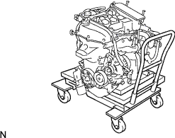
ENGINE ASSEMBLY INSTALLATION

-
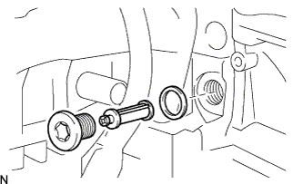
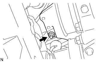
INSTALL E.F.I. ENGINE COOLANT TEMPERATURE SENSOR
Note
Do not use parts that have been dropped or received strong impact.
-
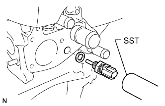
Using SST, install a gasket and the E.F.I. engine coolant temperature sensor.
- SST
- 09817-33190
- Torque:
- 19.6 N*m { 200 kgf*cm, 14 ft.*lbf }
-
Connect the water temperature sensor connector.
-
-
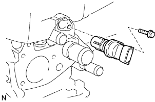
INSTALL CAMSHAFT POSITION SENSOR
Note
-
Do not use parts that have been dropped or received strong impact.
-
Make sure that the O-ring is not damaged before installing it.
-
Apply a light coat of engine oil to the O-ring.
-
Install the camshaft position sensor with the bolt.
- Torque:
- 7.5 N*m { 77 kgf*cm, 66 in.*lbf }
-
Connect the camshaft position sensor connector.
-
-
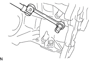
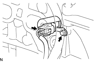
INSTALL KNOCK CONTROL SENSOR
-
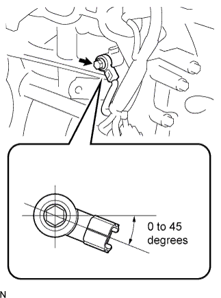
Install the knock control sensor with the bolt.
Tech Tips
Be sure to tilt the knock control sensor by 0 to 45 degrees as shown in the illustration.
- Torque:
- 20 N*m { 204 kgf*cm, 15 ft.*lbf }
-
Connect the knock control sensor connector.
-
-
INSTALL ENGINE OIL PRESSURE SWITCH ASSEMBLY
-
Install the engine oil pressure switch.
- Torque:
- 8.5 N*m { 87 kgf*cm, 75 in.*lbf }
Note
Use a wrench with a fulcrum length of 345 mm (13.58 in.)
Tech Tips
If a wrench with a fulcrum length of 345 mm (13.58 in.) is used, the torque should be 8.5 N*m (87 kgf*cm, 75 in.*lbf). If not, the torque needs to be calculated based on 15 N*m (153 kgf*cm, 11 ft.*lbf) tightening torque for the oil pressure switch assembly.
-
Connect the engine oil pressure switch connector.
-
-
INSTALL OIL CONTROL VALVE FILTER
-
Install the oil control valve filter to the straight screw w/ head plug.
-
Using a hexagon wrench, install a new gasket and the oil control valve filter.
- Torque:
- 24.5 N*m { 250 kgf*cm, 18 ft.*lbf }
-
-
INSTALL CAMSHAFT TIMING OIL CONTROL VALVE ASSEMBLY
Note
Make sure that the O-ring is not damaged before installing it.
-
Apply a light coat of engine oil to the O-ring.
-
Install the camshaft timing oil control valve assembly with the bolt.
- Torque:
- 10 N*m { 102 kgf*cm, 7 ft.*lbf }
-
Connect the camshaft timing oil control valve assembly connector.
-
-
INSTALL CRANKSHAFT POSITION SENSOR
Note
-
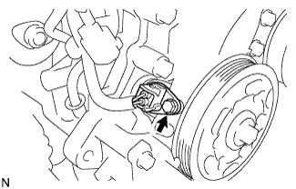
Do not use parts that have been dropped or received strong impact.
-
Make sure that the O-ring is not damaged before installing it.
-
Apply a light coat of engine oil to the O-ring.
-
Install the crankshaft position sensor with the bolt.
- Torque:
- 7.5 N*m { 77 kgf*cm, 66 in.*lbf }
-
Connect the crankshaft position sensor connector.
-
-
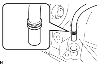
INSTALL THERMOSTAT
Note
Do not use the dropped water inlet.
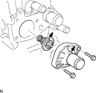
-
Install the thermostat gasket to the thermostat.
-
Install the thermostat with the jiggle valve upward.
Note
Make sure that the jiggle valve is aligned with the top protrusion of the water inlet.
-
Install the water inlet with the 2 bolts.
- Torque:
- 7 N*m { 71 kgf*cm, 62 in.*lbf }
Note
Make sure that the thermostat gasket does not get caught between the parts after installing the water inlet.
-
-
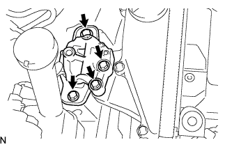
INSTALL INTAKE MANIFOLD
-
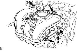
Install the intake manifold gasket to the intake manifold.
-
Install the intake manifold with the 4 bolts and 2 nuts.
- Torque:
- 30 N*m { 306 kgf*cm, 22 ft.*lbf }
Note
Tighten the bolts and nuts in the order shown in the illustration.
-
-
INSTALL VACUUM SENSOR
-
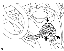
Install the vacuum sensor with the 2 bolts.
- Torque:
- 5 N*m { 51 kgf*cm, 44 in.*lbf }
-
Connect the vacuum sensor connector.
-
-
INSTALL FUEL INJECTOR
-
Install the fuel injector Click here.
-
-
INSTALL FUEL DELIVERY PIPE
-
Install the fuel delivery pipe Click here.
-
-
INSTALL THROTTLE BODY ASSEMBLY
-
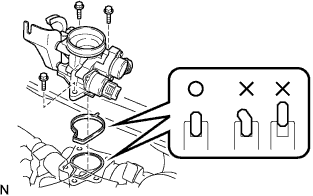
Install the throttle body gasket to the intake manifold.
-
Install the throttle body assembly with the 3 bolts.
- Torque:
- 10 N*m { 102 kgf*cm, 7 ft.*lbf }
Note
Do not bend the throttle body gasket while installing the throttle body assembly.
-
Connect the throttle body assembly connector.
-
-
INSTALL OIL LEVEL GAUGE GUIDE SUPPORT
-
Install the oil level gauge guide support.
Seal packing Part No. 08833-00070 or equivalent Note
Apply seal packing inside the cylinder block.
-
-
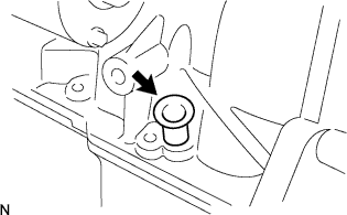
INSTALL OIL LEVEL GAUGE GUIDE
-
Install a new O-ring to the oil level gauge guide.
-
Apply a light coat of engine oil to the O-ring.
-
Install the oil level gauge guide with the bolt.
- Torque:
- 10 N*m { 102 kgf*cm, 7 ft.*lbf }
-
Connect the 2 clamps to the oil level gauge guide.
-
-
INSTALL OIL LEVEL GAUGE SUB-ASSEMBLY
-
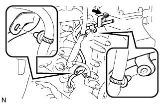
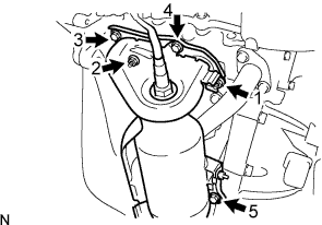
INSTALL WATER BY-PASS PIPE NO.1
-
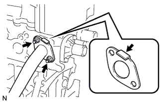
Install a new water by-pass pipe gasket and water by-pass pipe No.1 with the 2 nuts.
- Torque:
- 24 N*m { 245 kgf*cm, 18 ft.*lbf }
Note
Be sure to install the gasket in the direction shown in the illustration.
-
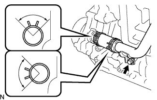
Install the water by-pass hose to the water by-pass pipe with the clip.
Note
-
Be sure to install the clip as shown in the illustration.
-
Be sure to insert the water by-pass hose to the stay edge of the water by-pass pipe.
-
-
Install the water by-pass pipe with the bolt.
- Torque:
- 24 N*m { 245 kgf*cm, 18 ft.*lbf }
-
-
INSTALL COMPRESSOR MOUNTING BRACKET NO.1 (W/ AIR CONDITIONER)
-
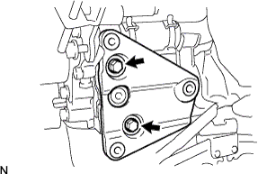
Install the compressor mounting bracket with the 2 bolts.
- Torque:
- 24.5 N*m { 250 kgf*cm, 18 ft.*lbf }
-
-
INSTALL EXHAUST MANIFOLD
-
Install the exhaust manifold gasket.
-
Install the exhaust manifold with the 3 bolts and 2 nuts.
- Torque:
- 24 N*m { 245 kgf*cm, 18 ft.*lbf }
Note
Tighten the bolts and nuts in the order shown in the illustration.
-
-
INSTALL FAN BELT ADJUSTING BAR
-
Install the fan belt adjusting bar Click here.
-
-
INSTALL GENERATOR ASSEMBLY
-
Install the generator assembly Click here.
-
-
INSTALL SPARK PLUG
-
Install the 3 spark plugs.
- Torque:
- 25 N*m { 255 kgf*cm, 18 ft.*lbf }
Note
Do not use parts that have been dropped or received strong impact.
-
-
INSTALL IGNITION COIL NO.1
-
Install the 3 ignition coils with the 3 bolts.
- Torque:
- 8.9 N*m { 91 kgf*cm, 79 in.*lbf }
-
Connect the 3 connectors.
-
-
INSTALL FLYWHEEL SUB-ASSEMBLY
-
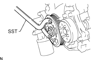
Using SST, hold the crankshaft.
- SST
- 09960-10010 ( 09962-01000, 09963-01000 )
-
Clean the bolts and their holes.
-
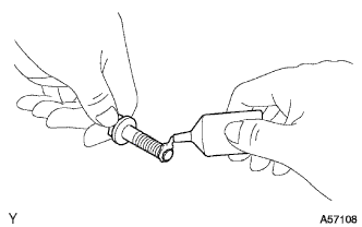
Apply adhesive to the 2 or 3 threads of the bolt end.
Adhesive Part No. 08833-00070, THREE BOND 1324 or equivalent -
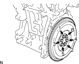
Install the flywheel sub-assembly with the 6 bolts.
- Torque:
- 78 N*m { 796 kgf*cm, 58 ft.*lbf }
Note
Tighten the bolts in the order shown in the illustration.
-
-
INSTALL CLUTCH DISC ASSEMBLY
- SST
- 09301-00210
-
Install the clutch disc assembly Click here.
-
INSTALL CLUTCH COVER ASSEMBLY
- SST
- 09301-00210
-
Install the clutch cover assembly Click here.
-
INSTALL MANUAL TRANSAXLE ASSEMBLY
-
Install the manual transaxle assembly Click here.
-
-
INSTALL STARTER ASSEMBLY
-
Install the starter assembly Click here, Click here.
-
-
INSTALL FRONT SUSPENSION CROSSMEMBER SUB-ASSEMBLY
-
Install the engine and transaxle assembly to the crossmember sub-assembly and the engine mounting member with the bolt.
- Torque:
- 120 N*m { 1,224 kgf*cm, 89 ft.*lbf }
-
-
INSTALL ENGINE ASSEMBLY W/ TRANSAXLE
-
Set the engine lifter.
-
Remove the chain block from the engine assembly with transaxle.
-
Remove the 2 engine hangers and 2 bolts.
-
Install the engine assembly with transaxle.
-
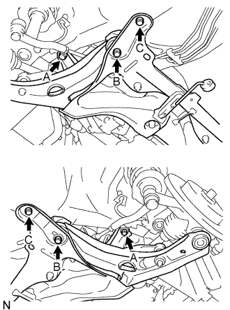
Tighten the 6 bolts.
- Torque:
- 85 N*m { 867 kgf*cm, 63 ft.*lbf, for A }
- 128 N*m { 1,306 kgf*cm, 95 ft.*lbf, for B }
- 48 N*m { 490 kgf*cm, 35 ft.*lbf, for C }
-
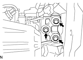
Install the engine mounting insulator LH with the 3 bolts.
- Torque:
- 52 N*m { 530 kgf*cm, 38 ft.*lbf }
-
Tighten the 4 bolts.
- Torque:
- 52 N*m { 530 kgf*cm, 38 ft.*lbf }
-
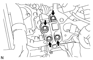
Install the engine mounting insulator RH with the nut.
- Torque:
- 52 N*m { 530 kgf*cm, 38 ft.*lbf }
-
Tighten the 4 bolts.
- Torque:
- 52 N*m { 530 kgf*cm, 38 ft.*lbf }
-
Remove the engine lifter.
-
-
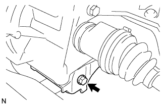
INSTALL FRONT DRIVE SHAFT ASSEMBLY RH
- SST
- 09930-00010
-
Install the front drive shaft assembly RH Click here.
-
INSTALL FRONT DRIVE SHAFT ASSEMBLY LH
- SST
- 09930-00010
-
Install the front drive shaft assembly LH Click here.
-
INSTALL FRONT SUSPENSION ARM SUB-ASSEMBLY LOWER RH
-
Install the front suspension arm sub-assembly lower RH Click here.
-
-
INSTALL FRONT SUSPENSION ARM SUB-ASSEMBLY LOWER LH
-
Install the front suspension arm sub-assembly lower LH Click here.
-
-
INSTALL TIE ROD END SUB-ASSEMBLY RH
-
Install the tie rod end sub-assembly RH Click here.
-
-
INSTALL TIE ROD END SUB-ASSEMBLY LH
-
Install the tie rod end sub-assembly LH Click here.
-
-
INSTALL FRONT AXLE HUB NUT RH
-
Install the front axle hub nut RH Click here.
-
-
INSTALL FRONT AXLE HUB NUT LH
-
Install the front axle hub nut LH Click here.
-
-
INSTALL FRONT WHEELS
-
INSTALL STEERING INTERMEDIATE SHAFT ASSEMBLY NO.2
-
Install the steering intermediate shaft assembly No.2 Click here.
-
-
INSTALL STEERING COLUMN HOLE COVER PLATE
-
Install the steering column hole cover plate Click here.
-
-
INSTALL CLUTCH RELEASE CABLE ASSEMBLY
-
Install the clutch release cable assembly Click here.
-
-
ADJUST CLUTCH RELEASE CABLE ASSEMBLY
-
Adjust the clutch release cable assembly Click here.
-
-
INSTALL TRANSAXLE CONTROL CABLE ASSEMBLY
-
Install the transaxle control cable assembly Click here.
-
-
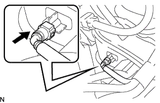
CONNECT FUEL TUBE SUB-ASSEMBLY
-
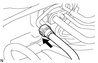
Align the connector with the pipe, then push in the connector to the pipe until it makes a click sound to connect the fuel tube sub-assembly to the fuel delivery pipe.
-
Install the fuel pipe clamp.
-
-
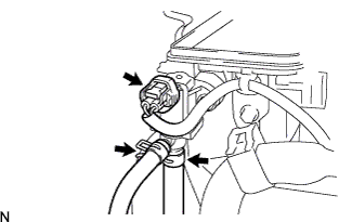
CONNECT HEATER WATER OUTLET HOSE A (FROM HEATER UNIT)
-
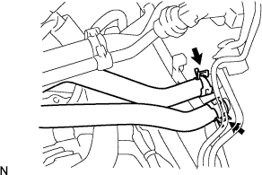
Using pliers, grip the claws of the clip and slide the clip to connect the heater water outlet hose A (from heater unit).
-
-
CONNECT HEATER WATER HOSE INLET A
Tech Tips
Connection procedure for the heater water inlet hose A is the same as for the heater water outlet hose A.
-
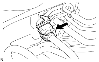
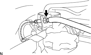
CONNECT VACUUM HOSE ASSEMBLY
-
Align the connector with the pipe, then push in the connector to the pipe until it makes a click sound to connect the vacuum hose to the intake manifold.
-
-
INSTALL W/ PULLEY COMPRESSOR ASSEMBLY (W/ AIR CONDITIONER)
-
Install the w/ pulley compressor assembly Click here.
-
-
INSTALL W/ MOTOR FAN ASSEMBLY
-
Install the w/ motor fan assembly Click here.
-
-
INSTALL RADIATOR ASSEMBLY
-
Install the radiator assembly Click here.
-
-
INSTALL FRONT CROSS MEMBER SUB-ASSEMBLY
-
Install the front cross member sub-assembly Click here.
-
-
INSTALL RADIATOR HOSE OUTLET
-
INSTALL RADIATOR HOSE INLET
-
INSTALL FRONT EXHAUST PIPE ASSEMBLY
-
Install the front exhaust pipe assembly Click here.
-
-
INSTALL FAN & GENERATOR V BELT
-
Install the fan and generator V belt Click here.
-
-
INSTALL FRONT BUMPER COVER
-
Install the front bumper cover Click here.
-
-
INSTALL FUEL VAPOR FEED HOSE NO.1 AND NO.2
-
Connect the VSV connector.
-
Connect the fuel vapor feed hoses No.1 and No.2.
-
-
INSTALL AIR CLEANER CAP SUB-ASSEMBLY
-
Connect the throttle control cable to the throttle body.
- Torque:
- 13 N*m { 133 kgf*cm, 9.6 ft.*lbf }
-
Install the air cleaner filter element to the air cleaner case.
-
Install the air cleaner cap sub-assembly.
-
Tighten the hose clamp bolt.
-
Engage the air cleaner cap sub-assembly clamp.
-
-
CONNECT ENGINE WIRE
-
Connect the battery terminal B with the nut.
- Torque:
- 14 N*m { 143 kgf*cm, 10 ft.*lbf }
-
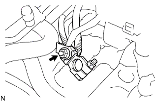
Connect the 2 ground terminals with the 2 bolts.
- Torque:
- 8.4 N*m { 86 kgf*cm, 74 in.*lbf }
-
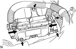
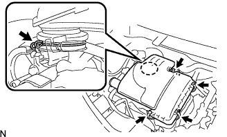
Install the ECM with the 3 bolts.
- Torque:
- 8 N*m { 82 kgf*cm, 71 in.*lbf }
-
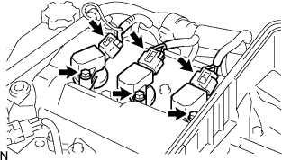
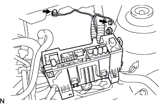
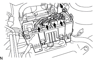
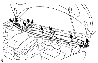
Connect the engine wire harness clamp.
-
Connect the engine wire harness connectors to the ECM.
-
Install the engine relay block with the bolt.
- Torque:
- 8.4 N*m { 86 kgf*cm, 74 in.*lbf }
-
Connect the engine wire harness connectors to the engine room relay block.
-
-
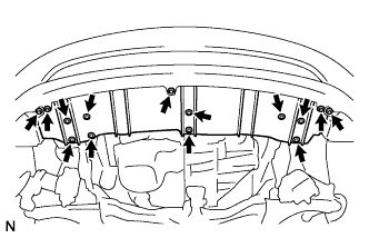
INSTALL COWL TOP PANEL OUTER
-
Install the cowl top panel outer with the 10 bolts.
- Torque:
- 9.2 N*m { 94 kgf*cm, 81 in.*lbf }
-
-
INSTALL FRONT WIPER MOTOR & LINK ASSEMBLY
-
Install the front wiper motor & link assembly Click here.
-
-
INSTALL COWL TOP VENTILATOR LOUVER RH
-
Install the cowl top ventilator louver RH Click here.
-
-
INSTALL COWL TOP VENTILATOR LOUVER LH
-
Install the cowl top ventilator louver LH Click here.
-
-
INSTALL HOOD TO COWL TOP SEAL
-
Install the hood to cowl top seal Click here.
-
-
INSTALL FRONT WIPER ARM LH
-
Install the front wiper arm LH Click here.
-
-
INSTALL FRONT WIPER ARM HEAD CAP
-
Install the front wiper arm head cap Click here.
-
-
INSTALL BATTERY
-
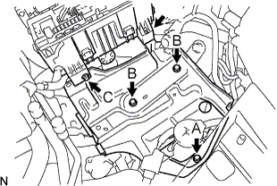
Install the battery carrier with the 4 bolts.
- Torque:
- 17.2 N*m { 175 kgf*cm, 13 ft.*lbf, for A }
- 7.4 N*m { 75 kgf*cm, 65 in.*lbf, for B }
- 8.4 N*m { 86 kgf*cm, 74 ft.*lbf, for C }
Tech Tips
Tighten the A bolt from the service hole on the battery carrier.
-
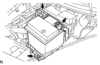
Install the battery clamp with the bolt.
- Torque:
- 15.1 N*m { 154 kgf*cm, 11 ft.*lbf }
-
Connect the positive battery cable.
- Torque:
- 5.4 N*m { 55 kgf*cm, 48 in.*lbf }
-
-
ADD MANUAL TRANSAXLE OIL
-
Add the manual transaxle oil Click here.
-
-
INSPECT MANUAL TRANSAXLE OIL
-
Inspect the manual transaxle oil Click here.
-
-
ADD ENGINE COOLANT
-
Add the engine coolant Click here.
-
-
INSPECT FOR ENGINE COOLANT LEAKS
-
Inspect for engine coolant leaks Click here.
-
-
INSPECT ENGINE OIL LEAKS
-
CONNECT BATTERY NEGATIVE TERMINAL
-
Connect the negative battery cable.
- Torque:
- 5.4 N*m { 55 kgf*cm, 48 in.*lbf }
-
-
INSPECT AND ADJUST FRONT WHEEL ALIGNMENT
-
Inspect and adjust the front wheel alignment Click here.
-
-
INSPECT CO/HC
-
Inspect the CO/HC Click here.
-
-
INSTALL ENGINE UNDER COVER
-
Install the engine under cover with the 5 screws.
-
Install the 9 bolts.
-